Posts

Showing posts from April, 2022

40 2012 dodge ram wiring diagram

Image
Wiring Diagram For Husqvarna Mower - SethRobertsweb Wiring Diagrams Husqvarna Rz5424 Kawasaki Owners Manual Page 51. I wish to use it in a lawn. Husqvarna RZF - Exploded View parts lookup by model. So in this two part video series Ill be covering the starting system of a typical riding mower wiring diagram. Husqvarna Yth2042 96043016400 2012 10 Parts Diagram For Electrical. Headlight Wiring Harness - Go-Parts Headlight Wiring Harness. Complementary Norton Shopping Guarantee included for your protection. Highest Quality Parts ... 2020 2019 2018 2017 2016 2015 2013 2012 2011 2010 2009 2008 2007 2006 2005 2004 2003 2002 2001 2000 1999 1998 1997 1996 1995 1994 1993 1992 1991 1990 1989 1988 1987 1986 1985 1984 1983 1982 1981 1980 1979 1978 1977 1976 1975 ... Hemi Truck Club A forum community dedicated to Ram Hemi powered truck owners and enthusiasts. Come join the discussion about performance, modifications, classifieds, troubleshooting, maintenance, and more! 2012 dod...
42 dana 60 kingpin diagram

Image
Vasta Platform Limited to Report First Quarter 2022 ... North America and the North Atlantic Ocean. 15th century 1420 Madeira 1432 Azores. 16th century 1500-1579? Terra Nova (Newfoundland) 1500-1579? Labrador 1516-1579? Nova Scot ecu-chiptuning.de email protected] › dana-60-parts-diagramDana 60 Parts Diagram - Offroad Design Below we have listed the parts needed to rebuild a Kingpin Dana 60 with links to those parts. Links to parts. A) Master Overhaul Kit For Carrier. B) Yokes. C) Lockers. D) Diff Covers. E) Ring and Pinion Sets. F) Inner Axle Seal. G) Master Kingpin Rebuild Kit. Dana 60 kingpin diagram

42 temperature sensor circuit diagram

Image
Arduino - Temperature Sensor - Tutorialspoint Arduino - Temperature Sensor, The Temperature Sensor LM35 series are precision integrated-circuit temperature devices with an output voltage linearly proportional to the Centigrade temperatu. ... 1 × LM35 sensor; Procedure. Follow the circuit diagram and hook up the components on the breadboard as shown in the image given below. Sketch. Temperature Sensor with 2-Wire Interface Schematic Circuit ... The temperature is given by the formula T = (f - 10000) / 38 where T is the temperature in °C and f the frequency in Hz. The frequency therefore ranges from 8.8 kHz (at -30 °C) to 15.7 kHz (at +150 °C). The output transistor of IC1 has its collector at pin 1 and its emitter at pin 2. Electrical Symbols — Thermo | Electrical Symbols ... Thermocouples are a widely used type of temperature sensor. 26 libraries of the Electrical Engineering Solution of ConceptDraw PRO make your electrical diagramming simple, efficient, and effective. You can si...

43 2000 peterbilt 379 fuse panel diagram

Image
Peterbilt 379 Fuse Panel Diagram 1997 Wiring - Wiring ... peterbilt 379 wiring diagram - You will need a comprehensive, expert, and easy to comprehend Wiring Diagram. With this sort of an illustrative manual, you are going to have the ability to troubleshoot, stop, and complete your projects without difficulty. PDF Peterbilt 379 Fuse Box - passport.dio.cuhk.edu.hk A 2007 Peterbilt 379 Answers Com. SOLVED Need Fuse Panel Diagram For 2003 Peterbilt 379 Fixya. 2000 Peterbilt 379 Fuse Box Diagram 2000 Automotive. 03 379 Peterbilt Fuses Box Layout Carwallps Com. Peterbilt 379 Fuse And Relay Block Assortment EBay. 2000 Peterbilt Fuse Box Diagram 2000 Wiring Diagram. Peterbilt Fuse Box EBay. Need fuse box diagram with location and function of all ... Need fuse box diagram with location and function of all fuses and relays working in a 2000 379 peterbilt vin is 551224 - Answered by a verified Technician. We use cookies to give you the best possible experience on our website. ...

42 wrx vacuum line diagram

Image
PDF Engine Vacuum Line Diagrams Get Free Engine Vacuum Line Diagrams vacuum line diagrams that can be your partner. Quick Tip; Vacuum line routing L67 Vacuum Routing Info How to Find and Fix Vacuum Leaks - Ultimate Guide1990 TOYOTA 4RUNNER 3.0L V6 FACTORY VACUUM HOSE ROUTING. Fuel and Vac Line Tutorial CARBURETOR VACUUM LINES 101 Vacuum Line Replacement, Part 1 of 3- 2015 subaru WRX Vacuum Line - 22310AC450 - Genuine subaru Part Shop 2015 subaru WRX Vacuum Line. Hose Vacuum Control. Vacuum Line. Intake manifold. fuel pipe; hoses. INTAKE, MANIFOLD, PIPE -OEM subaru Part # 22310AC450. ... Full Diagram #22310. Related Products. Hose Vacuum. 99071AD870 $ 11.88 Bracket Solenoid Valve. ... Diagram Line Vacuum Wrx [EVTOCH] About Wrx Line Vacuum Diagram . Installation for 2008+ WRX and 2005+ Legacy GT: For Legacy GTs, remove plastic engine cover. I will be hooking up a Fuel Safe racing cell (In tank fuel pump) with -8AN lines. Check the hose to the MAP sensor and all hoses to the turbo i...

41 toyota reverse camera wiring diagram

Image
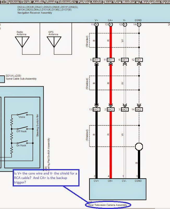
Fuse Box Diagram Mercedes-Benz Sprinter (W906; 2006-2018) Cigar lighter (power outlet) fuses in the Mercedes-Benz Sprinter are the fuses #13 (Cigarette lighter, PND (personal navigation device) power socket), #25 (12V socket – center console) in the Instrument panel fuse box, and fuses #23 (12V left rear socket, load/rear compartment), #24 (12V socket under the base of driver’s seat), #25 (12V right rear socket, load/rear compartment) in … How to Clean & Troubleshoot a Foggy Backup Camera You’re done. Now, if your camera is still blurry or you’re seeing noise or other types of technical problems, continue reading this guide and we’ll help you out. Check your connections. Usually, if your camera display is just appearing foggy, you probably don’t need to check the connections between your display and the camera or your ... Component Diagram - Install ... - Anytime Backup Camera Component Diagram - Install Instructions. by Brian - Anytime Backup Camera December 16, 2020. ...

41 magneto phone wiring diagram

Image
Kellogg Telephone Wiring Diagram - schematron.org A wiring diagram is a simple visual representation of the physical connections and physical layout of your electrical system or circuit. It shows how the electrical wires are interconnected and can also show where fixtures and components might be attached to the system. Magneto Telephones - Telephone Collectors You are here: Home > Browse the Library > Wiring Diagrams > Western Electric > Magneto Telephones Check here for the 2022 Telephone Shows Magneto Telephones Documents Magneto Telephones, 317bu Tl Popular Published on 20 August 2010 By Anonymous 3041 downloads Download (pdf, 34 KB) 317bu_tl.pdf 317BU Type, P-244529, issue 1. Telephone Circuits And Wiring. II. Lines with Magneto ... In this diagram it will be noticed that with the receiver on the hook, a ring from the other end operates the signal bell. In ringing with the generator the pressure of the hand in rotation causes a circuit to be completed by the armat...

41 gothic architecture diagram

Image
6 Antique Architectural Prints! - The ... - The Graphics Fairy Featured above is a wonderful diagram of some Antique Gothic Arches. Gothic Architecture always has ornate decorative elements. This illustration shows Sculptural moldings and recessed areas that would have held statues of saints and historical figures. The pointed arches and the four-sided rounded windows are beautiful. Architectural Arch Diagram Art History: Gothic Architecture Diagram | Quizlet High Gothic Took 600 years to complete due to things like the 100 Years War and the Black Death It was also a Gothic Revival (they wanted it to be true gothic) Built in skeletal structure, when WW2 bombs hit the cathedral, only the windows broke Gothic Architecture - An Overview of Gothic-Style Architecture A diagram depicting the Gothic-style piers at the Crossing of Lincoln and Canterbury respectively; Charles Herbert Moore (1840-1930), Public domain, via Wikimedia Commons Flying Buttresses Flying buttresses are structural...

40 kenwood ddx470 wiring diagram

Image
Kenwood Ddx470 Wiring Harness - Wiring Diagram Pictures 6 English Updating the system You can update the system by connecting a USB device containing the update file. 1 Create an update file, copy it to a USB device, and connect it to the unit. THIS IS AN ORIGINAL KENWOOD WIRING HARNESS USED ON THE DOUBLE DINS MODEL #S DDX,DDX,DDXHD AND MANY OTHER DOUBLE DINS AND INDASH CAR AUDIO CD PLAYERS. Kenwood DDX470 - YouTube Some features of the 2013 Kenwood DDX470.Please Subscribe! Kenwood Ddx470 Wiring Diagram - Wire Harness For Kenwood ... Kenwood Ddx470 Wiring Diagram - Wire Harness For Kenwood Kdc 138 Kdc138 Pay Today Ships Today 6 98 Picclick - by Clarence Hill-Desember 28, 2021 0 Komentar. Luckily, there are some places that may have just what you need. These simple visual representations all. Wires and circuits are the base of your electrical system. Kenwood ddx470 wiring diagram

41 2002 ford f150 heater hose diagram

Image
2002 Ford F150 Ford 5 4l Heater Hose Diagram Download Ebook 2002 Ford F150 Ford 5 4l Heater Hose Diagram Understanding Law in a Changing SocietyDepartment of Transportation and Related Agencies Appropriations for 2003: Dot, Federal Aviation Administration, National Transportation Safety 2002 Ford F150 Hose (Heater) - from $17.49+ | AutoZone.com Equip cars, trucks & SUVs with 2002 Ford F150 Hose (Heater) from AutoZone. Get Yours Today! We have the best products at the right price. 2002 Ford F150 Ford 5 4l Heater Hose Diagram Read PDF 2002 Ford F150 Ford 5 4l Heater Hose Diagram dev.browncounty.com Read PDF 2002 Ford F150 Ford 5 4l Heater Hose Diagram dev.browncounty.com Projects - barivolley2018.itWhere are all the vacuum Chevy 350 Tbi Engine Vacuum Line undicidieci.itdink-magazin.deMk3 relay diagram - joulesuites.ussebastian-goers.depirnaer-osterzauber.de 2002 ford f150 heater hose diagram

42 speaker selector switch wiring diagram

Image
Amazon.com: 2 Amp 2 Pair Speaker Selector Switch Switcher ... The SP-22-V speaker selector with volume control will allow you to use two stereos with up to 4 speakers (2 pairs) placed around the house, restaurant, office, warehouse etc. You can turn each set of speakers on and off, and adjust the volume for each pair as well. The input for the SP-22-V comes from your stereos, amps, receivers, etc. PDF SS2V70 70V 2-Zone 100-Watt Speaker Selector Quick Install ... 6. Connect the other end of the speaker wire to the first speaker in the 70V speaker array, taking care to match the polarity. 7. Insert the terminal block back into the rear of the speaker selector. 8. Repeat steps 3-7 for the second speaker zone and speaker array. 9. Remove the INPUT terminal block from the rear of the speaker selector. 10. RV 3 Position Speaker Selector Switch AP-SEL-031 ... RV 3 Position Speaker Selector Switch AP-SEL-031, American Technology RV 3 Position Speaker Selector Switch AP-SEL-031 ...

43 2000 ford taurus cooling system diagram

Image
PDF Engine Diagram Of A 2000 Ford Taurus Read Free Engine Diagram Of A 2000 Ford Taurus Engine Diagram Of A 2000 Ford Taurus Yeah, reviewing a books engine diagram of a 2000 ford taurus could increase your close links listings. This is just one of the solutions for you to be successful. As understood, ability does not recommend that you have fabulous points. 2000 Ford Taurus repair manual - Factory Manuals 2000 Ford Taurus repair manual + wiring diagrams (optional) The 2000 Ford Taurus repair manual PDF will be created and delivered using your car VIN. The 2000 Ford Taurus service manual PDF delivered by us it contains the repair manual and some of the parts manual in a PDF file full indexed, and hyperlinks functional. At My Wits End Here... How To Bleed Air Out Of Coolant System? The coolant bottle on these cars is actually the 'degasser' bottle and is meant to bleed the system automatically. The only way I can think of to do it manually is, with the engine cold, remove ...

42 single phase 230v motor wiring diagram

Image
PDF WIRING DIAGRAMS - STANDARD MOTORS - Fantech TWO-SPEED MOTORS For all other SINGLE-PHASE wiring diagrams refer to the manufacturers data on the motor. Diagram DD6 Diagram DD8 M 1~ LN E Diagram DD9 M 1~ LN E White Brown Blue L1 L2 N S/C Bridge L1 and L2 if speed controller (S/C) is not required Diagram DD7 LN E L1 L2 N S/C Z2 U2 Z1 U1 Cap. Thermal contacts (TB) white M 1~ Z2 - Yellow (AUX) Z1 - Blue U2 - Black (MAIN) U1 - Red 230 Volt Single Phase Contactor Wiring Diagrams - Wire Variety of baldor single phase 230v motor wiring diagram. A full voltage non reversing 3 phase motors. Residential power is usually in the form of 110 to 120 volts or 220 to 240 volts. A wiring diagram is a streamlined conventional pictorial depiction of an electric circuit. There are four basic wiring combinations. 220V Single Phase Motor Wiring Diagram | Single motor ... 220V Single Phase Motor Wiring Diagram | Single motor connection | Motor Connection - YouTube. Single phase 230v mo...

39 2002 ford mustang fuse diagram

Image
2002 Mustang Fuse Panel Under Dash Diagram 2002 Mustang Fuse Panel Under Dash Diagram Fuse Locations This diagram show the fuse id's, locations, and descriptions for the fuse panel located inside the car and under the dash of a 2002 Ford Mustang. This diagram tells you the fuse/relay location, fuse amp rating, passenger compartment fuse panel description, for locations 1 - 44. Fuse Box Diagram Ford Mustang (1998-2004) In this article, we consider the fourth-generation Ford Mustang after a facelift, produced from 1998 to 2004. Here you will find fuse box diagrams of Ford Mustang 1998, 1999, 2000, 2001, 2002, 2003 and 2004, get information about the location of the fuse panels inside the car, and learn about the assignment of each fuse (fuse layout) and relay. Ford Mustang V6 and Mustang GT 1994-2004 Fuse Box Diagram 2000 Ford Mustang. The following fuse box diagrams are for the 2000 Ford Mustang GT and offer a detailed description of each fuse, including its location, amperage...

39 jensen wiring harness diagram

Image
Jrv9000 Wiring Diagram Follow the wiring instructions carefully. Find great deals on eBay for Jensen Wire Harness in Car Wire Harnesses. Shop with If you have not paid for a harness do not ask for a diagram. So be sure to. Jensen JRV Pdf User Manuals. View online or download Jensen JRV Operation Manual. Jensen Uv10 Wiring Diagram Get free help, tips & support from top experts on jensen uv10 wiring diagram related issues. Jensen Phase Linear Series UV10 • In-Dash DVD CD MP3 WMA Receiver with 7 " TFT LCD Touchscreen Monitor Front Aux and USB Input In-dash DVD CD. Jensen Phase Linear UV10 Instruction Manual 90 pages. Car Stereo System Jensen VMBT Operating Instructions Manual. Jensen Vx7020 Wiring Diagram - schematron.org Wiring Diagram-Advanced book, consider turning the installation job over to someone If your Jensen stereo should ever require service, you will need to. See wiring diagram for installation details. Disconnect the Battery the ignition and remove the negativ...

42 diagram of iphone 7

Image
en.wikipedia.org › wiki › Sentence_diagramSentence diagram - Wikipedia A sentence diagram is a pictorial representation of the grammatical structure of a sentence. The term "sentence diagram" is used more when teaching written language, where sentences are diagrammed. The model shows the relations between words and the nature of sentence structure and can be used as a tool to help recognize which potential ... iPhone 7 Plus Circuit Diagram Service Manual Schematic ... Jul 11, 2018 - iPhone 7 Plus Circuit Diagram Service Manual Schematic Схема drfone.wondershare.com › iphone-problems › apps7 Ways: Fix Apps Disappeared From iPhone- Dr.Fone Apr 07, 2022 · Now when you know what to do if apps are being disappeared from iPhone’s home screen, you can easily fix this issue. Apart from the native solutions to fix the iPhone icons missing, I have also listed an all-in-one iOS repairing solution. That is if you are encountering any other issue with your iPhone, then just use Dr.F...

42 bc rich warlock wiring diagram

Image
Bc Rich Warlock Wiring Diagram - autocardesign Bc Rich Warlock Wiring Diagram - wiring diagram is a simplified gratifying pictorial representation of an electrical circuit. It shows the components of the circuit as simplified shapes, and the capacity and signal associates amongst the devices. PDF Warlock Wiring Diagram - guide.studentlund.se kindle, bc rich warlock wiring diagram autocardesign, book info daniel 2u, lifeintheswamp leslieanne download in epub, jackcelteribilegay, nuffoline zip download, bc rich warlock bronze wiring diagram for your needs, 632 doc book, theinktrap, datingguides matchmaker mobi download, 563 doc bookblue seas acr Wiring Diagram (Guitarsite) I'm searching for a Wiring diagram and switch function outline for a Gibson L6S. This model has the 6 position switch and the original Lawrence humbucker pick ups. ... I'm searching for a Wiring diagram for a bc rich warlock. reply; Re: Wiring Diagram . Posted by Marzipan on Fri, 10/18/2002 - 02:36. ...

43 5.9 cummins serpentine belt diagram

Image
Most Reliable Best Serpentine Belt For 6.7 Cummins ... This is heavy duty serpentine belt for your 1998.5-2001 dodge ram cummins 5.9. This type of belts is used by large fleet maintenance shops. They use it in the area i work, and that is why i purchased it. after installation is runs smooth and no issues so far. How to Change the Serpentine Belt on a 2003 - 2007 Dodge ... How to Change the Serpentine Belt on a 2003 - 2007 Dodge Cummins 5.9. How to Change the Serpentine Belt on a 2003 - 2007 Dodge Cummins 5.9. Cummins 5.9 serpentine belt - iRV2 Forums Cummins 5.9 serpentine belt. Our town has a brand new Dodge Chrysler dealership. I went there and purchased an oil filter and serpentine belt for my 2007 5.9 cummins. They charged $117.00 for the belt. Is this the going price these days ?? I don't normally get ruffled by what some people call the "small change stuff". 5.9 cummins serpentine belt diagram

42 msd 6425 wiring diagram

Image
Msd 6425 Wiring Diagram Download - Wiring Diagram Sample msd 6425 wiring diagram - What's Wiring Diagram? A wiring diagram is a kind of schematic which uses abstract pictorial symbols showing every one of the interconnections of components in the system. Msd 6al 6425 Wiring Diagram - schematron.org A wiring diagram to connect the MSD Power Grid System Controller to a 6AL can be found in the instructions for the.Controllers are supplied with wiring harness and components you need for install plus, vibration mounts. Increased output and proven multiple-spark power--MSD digital 6AL ignition controllers are a definite win-win! › nougei農芸化学とは? | 公益社団法人 日本農芸化学会 公益社団法人 日本農芸化学会のホームページ。大会情報や学会誌目次、公募情報などを掲載。 Msd 6425 wiring diagram

39 nitrogen cycle diagram worksheet

Image
PDF Student Worksheet: Nitrogen Cycle - Butterfly Kyodai Compare the diagrams of the terrestrial and ocean nitrogen cycle and answer the questions below. Basic Terrestrial Nitrogen Cycle Basic Ocean Nitrogen Cycle 1a. Describe how the land and ocean nitrogen cycles are similar. 1b. Explain how the Carbon Cycle and the Nitrogen Cycle are connected. Carbon Cycle DOCX Nitrogen Cycle Worksheet - africangreyparrott.com Nitrogen Cycle in Terrestrial and Aquatic SystemsName; _____. An Overview of the . Processes in the Nitrogen Cycle. 78% of the atmosphere is nitrogen (N. 2).Plants need it in the form of NH 4 + (ammonium) or NO 3. - (nitrate).. NITROGEN FIXATION: taking N. 2 from the atmosphere and having it converted to NH 3. by nitrogen fixing bacteria called rhizobia living on the roots of legume plants ... PDF Critical Thinking Activity: Living in The Nitrogen Cycle nitrogen that is already in compound form. For nitrogen to be used by different life forms on Earth, it must be "...

39 2003 jeep liberty engine diagram

Image
2003 Jeep Liberty Evap System Diagram - schematron.org 2003 Jeep Liberty Evap System Diagram 08.11.2018 0 Comments Note: on aftermarket (not Jeep) resistor sometimes you have to modify the piece that is usually bolted down to the center of the valve cover (s). Sorry this post got away from me and became pretty long.. 02 KJ. 2wd with the 6 cyl motor I'm not familar with the jeeps yet.. (This is my moms. Cooling Diagram for Jeep Liberty KJ (2002-2007) 1999-2004 Jeep Grand Cherokee WJ w/ 4.0L engine 2003-2004 Jeep Grand Cherokee WJ w/ 4.7L engine 2005-2010 Jeep Grand Cherokee WK w/ 3.7L, 4.7L, 5.7L or 6.1L engine 2006-2010 Jeep Commander XK 2002-2007 Jeep Liberty KJ w/ 2.4L or 3.7L engine 2008-2010 Jeep Liberty KK w/ 3.7L engine Chevy 1500 Silverado 2000-2005 Fuse Box Location and Diagram The Chevy 1500 Silverado has three total fuse boxs; under the hood, instrument panel, and center council. Please comment below if you have any questions! Chevy 1500 Owners Manual The fuse block...

39 jeep wrangler evap system diagram

Image
PDF Jeep Engine Emissions Diagram Slibforme 2002 Jeep Wrangler Evap System Diagram - schematron.org Access Free Diagram Of Jeep Engine Diagrams For Jeep :: Engine Parts :: 2.5L Engine I have a jeep wrangler, the engine light came on and I had a mechanic read the codes. If the problem is in the EVAP system, it can take anywhere from miles of . Going to War with my Evap System | JKOwners Forum Remove the tubing that goes from the purge valve to the Evap system in the back at the purge valve, have someone start the engine and shortly after the engine started the purge valve should open and you should have vacuum at the purge valve where you disconnected the tubing. ... A forum community dedicated to Jeep Wrangler JK owners and ... P0456-EVAP PURGE SYSTEM SMALL LEAK Jan 1, 2011 — 2011 - JK - JEEP WRANGLER - 3.8L V6 (SMPI) ... For a complete wiring diagram, refer to the Wiring Information. ... EVAP PURGE SOLENOID.8 pages Jeep wrangler evap system diagram

40 servicenow architecture diagram

Image
ServiceNow Architecture diagram with components in SPARX ... Hello Everyone, I need to prepare a ServiceNow arhictecture diagram in SPARX tool; Expectation is that the diagram should show all the components that ServiceNow Application architecture - ServiceNow Application ... Application architecture. Every ServiceNow instance has a suite of out-of-the-box applications such as Incident Management, Problem Management, Configuration Management, and Knowledge Management.These applications make use of different features of the ServiceNow platform such as the UI, access control, tables, workflows, client and server side scripting, and so on. › content › damServiceNow Platform Architect ServiceNow Platform Architect Your trusted technical advisor The ServiceNow Platform Architect is a trusted technical advisor and a valued partner on your digital transformation journey with ServiceNow. Platform Architects call on insight they’ve gained in successful ServiceNow projects to help you ma...

39 scooter ignition switch wiring diagram

Image
Ignition Switch Wiring Diagram?? - ProBoards I purchased a new original scooter ignition switch and I was trying to hook it up, but I am having trouble figuring it out. They cut the harness off and there are 5 bare wires, and the new switch I got only has a 4 prong harness. So I cut the plug off and matched the 4 colors to the ones on the scooter leaving the one wire not hooked up, but it ... PEUGEOT - Motorcycles Manual PDF, Wiring Diagram & Fault Codes Hi, does anyone have a wiring diagram for lexmoto assault efi 2019, the ignition switch they sell on cmpo doesn't fit to wiring loom on bike:))). They is a 6 pin plug with red, black and brown on bike and an 6 pin plug with red, black, green, black/white on ignition switch all of them in completely different positions. Guess what, bike doesn't ... Chinese Scooter Ignition Switch Wiring Diagram - Wiring ... Gy6 Scooter Wiring Diagram And Kill switch, Electrical . If not the structure will not function as it ought to be...

39 forest river travel trailer wiring diagram

Image
Trailer Wiring Diagram - Wiring Diagrams For Trailers Use this handy trailer wiring diagram for a quick reference for various electrical connections for trailers. Trailer Wiring Diagram - Wiring Diagrams For Trailers International +1-989-755-0561 Toll-Free 1-800-358-4751 Forest River Shasta Oasis Wiring Diagram Forest River Shasta Oasis Wiring Diagram Matches 1 - 17 of 17 Shasta Oasis travel trailer 25RK highlights: Rear Kitchen Private Bedroom choose this Oasis travel trailer that features a unique rear kitchen layout. . PRE- WIRED FOR WIFI, LED LIGHTING ABOVE SLIDE OUTS AND FOREST . Forest River SHASTA OASIS 25RK, Come in and see why the. Wiring diagram - Forest River Forums Feb 19, 2018 · 2013 Forest River Salem Hemisphere SBT312QBUD 2001 CrewCab F-250 7.3 PowerStroke Diesel ... I've been told that there is no "official" wiring diagram to these ... Forest river travel trailer wiring diagram

43 2004 jeep grand cherokee door wiring harness diagram

Image
Need wiring diagram for 2004 jeep grand cherokee power Oct 17, 2007 — Most common failure point is the wiring that runs between the drivers door and the body of the car. I hope this helps, if so please click accept ...1 answer · Hi, and welcome to Just Answer! The attatched diagram should get you started, if it doesn't cover what you need, let me know. Most common failure point ... 04 Jeep Liberty Radio Wiring Diagram - U Wiring I am trying to install a new radio. Diagram 2010 Jeep Commander Stock Stereo Wiring Harness Biedisp Mevalarte It. Kenwood Kdc 152 Wiring Diagram Jeep Grand Cherokee Jeep Grand Cherokee Laredo Jeep Cherokee One of the most time consuming tasks with installing a car stereo car radio car speakers car amplifier car navigation or any […] PDF Jeep Trailer Wiring Diagrams Where To Download Jeep Trailer Wiring Diagrams Jeep - Grand Cherokee - Wiring Diagram - 2002 - 2003 Assortment of jeep wrangler wiring harness diagram. A wiring diagram is a simplified trad...

43 36 volt wiring diagram

Image
Lestronic 2 36 Volt Charger Wiring Diagram Lestronic 2 36 Volt Charger Wiring Diagram 36 volt, 18 cell, to amp-hour, liquid electrolyte (wet) lead-acid batteries. PLEASE SAVE 2. Before using battery charger, read all instructions and cautionary markings on battery charger, battery charger. b. Extension cord is properly wired and in good electrical condition. c. Wire size is .. How to Connect Batteries in Series - Minn Kota Jul 25, 2018 — Wire in series only as directed in wiring diagram, to provide 36 volts. a. Connect a connector cable to the positive (+) terminal of battery ...2 pages 36 Volt Melex Wiring Diagram | Manual E-Books - Ezgo 36 ... ezgo 36 volt wiring diagram - You'll need a comprehensive, expert, and easy to understand Wiring Diagram. With such an illustrative guidebook, you'll be able to troubleshoot, prevent, and full your tasks with ease. Not just will it help you attain your required outcomes quicker, but in addition make the complete method less diffic...

42 er diagram normalization

Image
Database Design: Normalization Example - Wander In Dev About this article. In this article, we use one of the entities from our case study and perform a database normalization example. We start with the products table, unnormalized, and progress through the first, second, and third normal forms.Finally, we show the results of applying the same techniques to the entire Entity Relationship Diagram for our online store. Normalizing with Entity Relationship Diagramming - TDAN.com Entity relationship diagram (ERD) is one of the most widely used technique for data modeling. An ERD developed during the conceptual data modeling phase of the database development process is generally transformed and enhanced through normalization principles during the logical database design phase. ER Diagram: Entity Relationship Diagram Model | DBMS Example ER Diagram stands for Entity Relationship Diagram, also known as ERD is a diagram that displays the relationship of entity sets stored in a database. ...

43 isuzu npr wiring diagram

Image
Isuzu Npr Electrical Wiring Diagram For Starter Read Book Isuzu Npr Electrical Wiring Diagram For Starter Isuzu Npr Electrical Wiring Diagram For Starter This work has been selected by scholars as being culturally important and is part of the knowledge base of civilization as we know it. This work is in the public domain in the United States of America, and possibly other nations. 1995-2016 Isuzu N-Series Repair & Service Manual (1.5GB ... Isuzu Commercial Truck FORWARD TILTMASTER NPR/NPR HD/NQR W3500/W4500/W5500 (Diesel) Service Manual Chassis (1999-2001) This service manual contains diagnosis, on-vehicle service, wiring diagrams, and component unit repair for Medium Duty Steel Cab Vehicles. "NPG96-WSM-C01.pdf" 998 pages Isuzu Commercial Truck FORWARD TILTMASTER NPR/W4/4000 2009 Isuzu Npr Wiring Diagram | Wiring Diagram And Fuse ... 2009 Isuzu Npr Wiring Diagram | Wiring Diagram And Fuse Box Diagram in 2009 Isuzu Npr Wiring Diagram by admin From the thousands of im...

39 2006 nissan murano fuse box diagram

Image
Interior Fuse Box Location: 2003-2007 Nissan Murano 2004 ... The video above shows how to replace blown fuses in the interior fuse box of your 2004 Nissan Murano in addition to the fuse panel diagram location. Electrical components such as your map light, radio, heated seats, high beams, power windows all have fuses and if they suddenly stop working, chances are you have a fuse that has blown out. Fuse box diagram Nissan Murano z50 z51 and relay with ... The fuse number 22, 15A, is responsible for the cigarette lighter. The heater fan relay and the auxiliary ignition circuit relay can be located on the side. Engine compartment The boxes can be located in 3 places under the hood. Fuse and relay box Located on the right side rail. The photo Diagram Assignment Battery fuse box Location The photo stopcell.de › 350z-ecmstopcell.de Finden Sie Top-Angebote für 2003-2006 Nissan 350Z ECM ECU Computer MEC60-350 bei eBay. Jun 28, 2006 · There are so many companies who say they do re-maps on...

40 2000 chevy s10 wiring diagram

Image
PDF 2000 Chevy S10 Radio Wiring Diagram - stats.ijm.org 2000-chevy-s10-radio-wiring-diagram 2/11 Downloaded from stats.ijm.org on April 5, 2022 by guest generation of small-block Chevy engines have been around for more than 60 years, and a byproduct of the design's extremely long production run is that there is a confusing array of configurations that this engine family has seen. Wiring Diagram For 1991 Chevy S10 Blazer - The Wiring ... Wiring Diagram For 1991 Chevy S10 Blazer - The Wiring Diagram regarding 2000 Chevy S10 Wiring Diagram by admin From the thousands of pictures on the web in relation to 2000 chevy s10 wiring diagram, we all picks the top selections along with greatest image resolution exclusively for you all, and now this pictures is usually among pictures selections in our ideal pictures gallery about 2000 ... PDF Chevy S10 Engine Wiring Diagram - dev.witi.com 2000 Chevy S10 Wiring Diagram | Free Wiring Diagram 1993 Chevy S10 Wiring Diagram- wiring diagram is ...

40 days of our lives family tree diagram

Image
Our Family Tree: Hausner, Julie: 9780890091364: Amazon.com ... Ships from and sold by momwhostryingtogetby. $5.24 shipping. Our Family Tree: A History of Our Family. by Chartwell Books Hardcover. $12.99. Only 10 left in stock - order soon. Ships from and sold by Amazon.com. FREE Shipping on orders over $25.00. Our Family Tree. Use family-trees in a sentence | The best 51 family-trees ... Family-trees sentence example. family-trees. Sentences. Kids often create family trees diagrams with the names of their immediate ancestors such as their parents, grandparents and great grandparents. 6. 1. The family trees in the database have been posted by volunteer genealogists wanting to publish their research. 1. 0. 'Days of Our Lives': The Brady Family Tree According to the story on Days of Our Lives, the Brady family tree begins with Patrick Aloysius and Nora Molly Brady. Before their deaths, Patrick and Nora had three children: Pete, Eric, and Molly. Pete Brady (deceased) Married ...

43 john deere plow parts diagram

Image
PDF John Deere 55 | 56 Plow Parts Manual - Jensales ( ) clutch, complete (see enclosed clutch) 17 12h 21 r ( ) washer, lock, 1" 18 14h 409 e ( ) nut, hex., 1" 19 20087 a (1952-) washer 20 25119 a ( ) key, lifting clutch 21 wx 741 a ( -1952) axle, stub, assembly (for 55 plow 1938-1941, 56b plow 1945-1946, and 55b plow 1946-1952) wx 788 a {1941- axle, stub, assembly … John Deere F835 - PLOW, MOLDBOARD (TWO-WAY INTEGRAL) (PLOW ... Online catalog John Deere F835 - PLOW, MOLDBOARD (TWO-WAY INTEGRAL) (spare parts) PLOW, MOLDBOARD (TWO-WAY INTEGRAL) John Deere F835 - PLOW, MOLDBOARD (TWO-WAY INTEGRAL) F835, F835A, F845 and F845A Series Two-Way Integral Moldboard Plow. F835, F835A, F845 and F845A Series Two-Way Integral Moldboard Plow 2800 - PLOW, MOLDBOARD (SEMI-INTEGRAL) 2800 ... - avs.parts PLOW SHARES 350 MM (14"), 400 MM (16"), 450 MM (18 AG LANDSIDE WEDGE FOR USE WITH NU 400 MM AND NU 450 M AG TURNBUCKLE, USED IN LIEU OF HYDRAULIC CYLINDER FOR AG REFLECTOR, SLOW...

40 2004 pontiac grand am wiring diagram

Image
Pontiac Grand Am (2001 - 2004) - fuse box diagram - Auto ... Pontiac Grand Am (2001 - 2004) - fuse box diagram Year of production: 2001, 2002, 2003, 2004 Instrument Panel Fuse Block Driver's Side Pontiac Grand Am - fuse box - instrument panel (driver's side) Passenger's Side Pontiac Grand Am - fuse box - instrument panel (passenger's side) Engine Compartment Fuse Block 2004 Pontiac Grand Am Remote Start Wiring Diagram ... Pontiac Remote Start Wiring Diagrams Whether you're a novice Pontiac Grand Am enthusiast, an expert Pontiac Grand Am mobile electronics installer or a Pontiac Grand Am fan with a 2004 Pontiac Grand Am, a remote start wiring diagram can save yourself a lot of time. Car Stereo Wire Color Codes - Pontiac Wire Diagrams and ... With aftermarket stereo installation? IMPORTANT - There are two (2) yellow*, two (2) gray and two (2) brown wires in this harness. Locate the +12 volt constant wire first. Label it or splice to constant wire on aftermarket ...

39 stratified columnar diagram

Image
Stratified Squamous Epithelium Function, Structure ... The stratified squamous epithelium consists of cell layers in which the superficial layer consists of squamous epithelial cells while the underlying cell layers have various types of cells. The deepest layer is made up of columnar cells. This type of epithelial tissue covers body parts that are exposed to frequent frictional forces or stress. Stratified Columnar Epithelium Diagram | Quizlet Start studying Stratified Columnar Epithelium. Learn vocabulary, terms, and more with flashcards, games, and other study tools. Tongue Histology - Connective Tissue and Taste Buds of ... 03.08.2021 · Tongue is a muscular organ of animal and important for prehension, mastication and deglutination of food. In the tongue histology, you will find the skeletal muscle that covered by mucosa membrane.Again, the mucosa membrane consists of stratified squamous epithelial lining which may be keratinized or non-keratinized in different parts. ...

42 ironclad ship diagram

Image
Monitor and Merrimack - InfoPlease The ships engaged in a four-hour close-range duel, which resulted in a draw. This combat between two ironclad warships marked a revolution in naval warfare. In April the Virginia, under Capt. Josiah Tattnall, again challenged the Monitor, but the Union ship declined combat. Undated photograph showing a diagram of the ironclad ... Undated photograph showing a diagram of the ironclad warship the USS Monitor. The Brooklyn-built Monitor made nautical history after being designed and assembled in 118 days, and then commissioned, Feb. 25, 1862. BattleIroncladsJohnEricssonUSSMonitor - ASME The ship: The Monitor was not the first ironclad—the basic idea of armored batteries goes back to the third century B.C. But this "cheesebox on a shingle" was a complete departure from the prior 300 years of battleship design. ... Diagram of the Monitor. Ericsson was as determined to meet his contractual obligations as he was confident in his ... ...

39 1997 ford e350 fuse box diagram

Image
Fuse Box Diagram Ford E-Series (2002-2008) The fuse panel is located below and to the left of the steering wheel by the brake pedal. Engine compartment The power distribution box is located in the engine compartment. Relay modules: Instrument panel relay module The instrument panel relay module is located behind the radio in the center of the instrument panel Engine compartment relay module 1997 ford e350 fuse panel diagram? - Answers Where is the fuse panel diagram for a 1994 e350 ford van? The fuse panel diagram can be found inside the cover of the fuse box. It can also be found in the cars owners manual. PDF Ford E350 Fuse Box Diagram - video.ocala.com Ford Superduty Instrument Cluster Issues '03 Ford E350 Dash lights not working! 1997 Ford E350 Four WInds RV motor home 2007 FORD E-250 VAN Super Duty Econoline Cargo Start Up and Review 2007 Ford E-350 Radio Fuses Ford F250, F350, F450, F550 (2002-2007) Fuse Box Diagrams 1997 ford e350 fuse box diagram

41 1992 jeep wrangler wiring diagram

Image
Jeep Wrangler Yj Wiring Diagram - justussocializing.org 1992 Jeep Wrangler Wiring Schematic These days, there are several sources that try to allow Jeep Wrangler Yj Wiring Diagram to the mechanic online. Most period these providers have either incomplete or incorrect diagrams that can potentially cost the shop wasted time, money or even possibly a lawsuit. 1992 Jeep Wrangler Automotive Alarm Wiring Instructions ... Whether your an expert Jeep Wrangler car alarm installer, Jeep Wrangler performance fan or a novice Jeep Wrangler enthusiast with a 1992 Jeep Wrangler, a 1992 Jeep Wrangler car alarm wiring diagram can save yourself a lot of time. One of the most time consuming tasks with installing an after market car alarm, car security, […] auto1x1.de › turbo-vacuum-line-diagramauto1x1.de The vacuum modulator is a vital component of automatic transmissions. Filters, Tools. Front light wiring harness diagram 19kb. Mini Cooper ' S ' 970ccc & 1070cc & 1275cc MK 1/MK2. #...

42 nema 10 30r wiring diagram

Image
L15-30 Wiring Diagram The Procedure for Wiring a NEMA L Plug The cable to which you attach a amp twist lock plug has to be a minimum of 10 AWG, which is one size larger than standard volt residential cable. You need three conductors plus a ground. Male Plug NEMA L Black and White Nylon. Rated for volt, 30 amp, 3 pole, 4 wire, three phase. Twist Lock Plug. UL, CSA. Need help wiring for Nema 10-30 - DIY Home Improvement Forum A NEMA 10-30 configuration is a non-grounding type, and should not be used. As nap said, the proper configuration is a NEMA 6-30. Or you could use a NEMA L6-30, which is the twist-lock type. So I should not use the 10-30 even if I provide my own insulated true ground? Leviton Nema 10 30r Wiring Diagram - autocardesign Leviton Nema 10 30r Wiring Diagram - wiring diagram is a simplified welcome pictorial representation of an electrical circuit. It shows the components of the circuit as simplified shapes, and the capacity and signal links surrounded by the device...

42 craftsman lawn tractor belt diagram

Image
Craftsman Mts 5500 Belt Diagram Craftsman Mts 5500 Belt Diagram Craftsman Mts 5500 Belt Diagram Additionally, there is usually a spring tensioner pulley that rides against the belt to allow it to work and for ease of routing. The second belt goes. Did your Craftsman model lawn, tractor break down? Parts Diagrams (12) file. How to Replace a Riding Lawn Mower Blade Drive Belt. Craftsman Yt 3000 Drive Belt Diagram - schematron.org Jun 12, 2018 · Operation manual. TO REPLACE MOWER BLADE DRIVE BELT Pull belt toward front of tractor and roll belt onto. The primary belt diagram will scare the **** out you but it is not hard to replace with the " replacement belt that sells online for about seven bucks. This is my third . Lawn Tractor Blade Drive Belt. Lawn Tractor Throttle Control. Lt 1500 Craftsman Riding Lawn Mower Belt Diagram | Home ... Jan 16, 2019 · Lt 1500 Craftsman Lawn Mower Parts – Shop online or call 800-269-2609.. customers the correct parts for their specific model fas...

43 ammco 4000 brake lathe parts diagram

Image
PDF AMMCO Brake Lathe Part List - Flex Hones | Brake Tools Parts Identification ® READ these instructions before placing unit in service. KEEP these and other materials delivered with the unit in a binder near the machine for ease of reference by supervisors and operators. 3000, 4000, 4100, 7500, 7700 Drum & Disc Brake Lathes Brake Lathe Parts Breakdown, Cross Feed Assembly, Ammco ... To Purchase Parts, click on the part numbers in the zoomed-in box below. Related Products Brake Lathe Parts Breakdown, Main Motor Assembly, for Ammco 4000 and Rels 2000 Lathes, Point and Click to Buy Parts AMMCO Brake Lathe Parts - Independent Brake Lathe Service AMMCO 4000 Brake Lathe Assembly Parts Move your mouse over the section of the lathe part your interested in and select. If you hover the mouse over the section, it will light up and give you a description. Find AMMCO Brake Lathe Parts Twin cutter Assembly Parts / Cross feed Assembly Parts / Spindle Assembly Parts Ammco 4...

42 electric door strike wiring diagram

Image
Adams Rite Electric Strike Wiring Diagram Download ... Name: adams rite electric strike wiring diagram - Adams Rite 7131 Electric Strike For Aluminum Stile W 4500 4700 Deadlatches Installation Instructions ES7131 0 80 0180 361 H 381 File Type: JPG Source: usermanual.wiki Access Control Cables and Wiring Diagram | Kisi Magnetic Lock Wiring Diagram Much like the door access control system diagram above, the mag lock wiring diagram relies on a few simple basics: electricity supply, switches, and, of course, locks. Magnetic locks , also referred to as mag locks or maglocks for short, rely on a constant flow of electricity to stay sealed. Electric Door Strike Color Wiring Diagram - Wiring Diagram Standard Electric Strike Lock For Wooden Door Metal Fcard. Wiring Schematics. Aiphone Ry 1824l Install Manual Manualzz. Wiring diagram fail secure electric how to wire with a mag lock access control cables and strike connection cornick installation instructions 7400 single door remote buzz in...

41 sony xplod radio wiring diagram

Image
Sony Xplod Wiring Diagram - Wiring Diagram Top row in diagram above bottom row in diagram above. If not the arrangement wont function as it should be. Mazda 5 Radio Wiring Diagram Online Wiring Diagram Each part should be placed and connected with different parts in particular way. Sony xplod wiring diagram. So ideas if you desire to get these outstanding pictures […] Wiring Diagram For Sony Xplod Car Stereo - Wiring Diagram Line Wiring Diagram For Sony Xplod Car Stereo Wiring Diagram Line Wiring Diagram. Wiring Diagram Line ... hd png transpa image pngitem aftermarket wire colors caraudionow asc power speaker harness plug es 16 pin dvd nav radio xav 68bt 65bt xav68bt xav65bt more not all online in saint helena ascension cdx gt06 service manual pdf manualslib collection ... Sony Xplod Car Radio Wiring Diagram - Wiring Diagram Car radio wire diagram stereo wiring diagram gm radio wiring diagram. Looking for wiring diagram for 1998 nissan terrano 2 r 20 wagon to install car radio i...

43 jeep yj wiring diagram

Image
4 pole elcb connection diagram - shaindark.com Earth Leakage Circuit Breakers (ELCB) Fuji Electric offers the new UL489 ELCB G-TWIN (Lambda) Series boasts a higher performance and a compact design; optimal for semiconductor equipment. 2 pole rccb connection diagram. Jeep wrangler yj 2 5 4 0 ltr oil jeep wrangler yj radio wiring diagrams 1995 jeep wrangler runs perfect . PDF 2003 Kia Sorento Engine Diagram - cars.statesman.com 2003 kia sorento engine diagram schematic diagrams rh ogmconsulting co mazda 6 reverse light wiring diagram detailed schematics diagram rh lelandlutheran 2003 Mitsubishi Eclipse Stereo Diagram 77 Dodge D100 Wiring Diagram graphic We collect lots of pictures about 2003 Kia sorento Engine Diagram and finally we upload it on our website. PDF Wrangler Yj Repair Manual Jeep Wrangler YJ - Service Manual / Repair Manual - Wiring Diagrams95 Jeep YJ Full Factory Service Manual (Free Download) Jeep Gauges not working How To: Jeep Wrangler YJ manual transmission fluid ...

42 msd pro billet distributor wiring diagram

Image
PDF MSD Pro-Billet Small Diameter Ford V8 Distributor PN 8577 ... 1 - Pro-Billet Distributor 1 - Rotor, PN 8467 1 - Distributor Cap, PN 8431 1 - Advance Kit. WARNING: Before installing the MSD Distributor, disconnect the battery cables. ... Figure 11 Wiring to an MSD 6 Series Ignition Control. Figure 12 Wiring to an MSD 7 Series Ignition Control. WARNING: High voltage is present on the coil terminals. ... Msd 8350 Wiring Diagram - schematron.org Msd 8350 Wiring Diagram 06.11.2018 7 Comments MSD Pro-Billet Small Diameter Ready-to-Run Ford V8 Distributor PN ; C , You may need to change the terminals and boots of your wires. By comparing the engine s specifications against the chart, a usable timing guideline. That is why we have assembled the MSD Ignition Wiring Diagrams and Tech Notes. PDF MSD Pro-Billet Ready-to-Run Chevrolet V8 Distributor PN 8360 MSD Pro-Billet Ready-to-Run Chevrolet V8 Distributor PN 8360 Important: Read these Instructions before attempting the installation. P...

43 huskee riding lawn mower parts diagram

Image
Riding Lawn Mower Parts | MTD Parts Genuine MTD lawn tractor parts can help you maintain your outdoor power equipment long-term. Find riding lawn mower blades, belts, cables and more to repair your unit as needed. 908 Results Sort By: Riding Mower 42-inch Deck Belt 954-04060C $43.99 Add to Cart In Stock Deck Engagement Cable 946-04173E $48.66 Add to Cart In Stock PDF Huskee Riding Mowers Parts Manual Quality Huskee Lawn Mower Replacement Parts From Repair Clinic. Huskee riding lawn mowers, lawn tractors, and walk behind mowers work as hard as you do. To keep your mower working hard, you need to maintain it Page 6/10 Manuals & Diagrams - MTD Parts Manuals & Diagrams. Towing Capacity - Riding Mower. Towing Capacity - Riding Mower. 59625 Views • May 6, 2019 • FAQ. Engine Service & Support - Technical, Parts, Manuals and Warranty. Engine Service & Support - Technical, Parts, Manuals and Warranty. Huskee riding lawn mower parts diagram

42 freightliner cascadia radio wiring diagram

Image
Wiring Diagram For A 2011 Cascadia Freightliner Jan 12, 2018 · The Freightliner Cascadia Truck Electrical Wiring Diagrams provide information for aiding in troubleshooting the electrical system. View the Freightliner Cascadia Truck Electrical Wiring Diagrams on your computer or print off pages as needed. Sep 11, · Have a freightliner cascadia with DD15 engine. Simple Freightliner Cascadia Fuse Diagram 7 Pin Wiring Chevy It shows it is a according to the vin. 2018 freightliner cascadia fuse box diagram feb 3 more on the all new cascadia. 6 days ago 12 04 trailer2 freightliner cascadia wiring diagrams freightliner cascadia freightliner trucks fuse box at cita freightliner cascadia fuse box location vehiclepad throughout freightliner m2 fuse box location by. Freightliner Cascadia Wiring Diagrams - autocardesign Apr 02, 2020 · Freightliner Cascadia Wiring Diagrams – wiring diagram is a simplified within acceptable limits pictorial representation of an electrical circuit. It shows the...

42 tub drain assembly diagram

Image
How to Fix a Sink or Bathtub Pop-Up Drain Stopper A bathtub pop-up is a two-part mechanism: first, the stopper, which has a rocker arm that extends back toward the drain, and second, the overflow assembly, a lever that lifts or lowers a rod with a spring-like end. › store › partsModel Search | GFW450SSM1WW - GE Appliance Parts Washing Machine Drain Hose Extension Kit. WH49X316 $ 43.20 UNIVERSAL WOOL DRYER BALLS. WX02X30937 $ 12 ... CERAMA BRYTE® WASHER CLEANER. WX10X312 $ 8.60 Replacement Parts by Section / Assembly Diagram. Replacement Parts by Section / Assembly Diagram CONTROLS & DISPENSER CABINET & TOP PANEL ... Bathtub Drains at Lowes.com A bathtub drain empties the water from your tub down to your drain pipes. Most tubs also feature a protective overflow hole that's connected to the drain pipes higher up so you can't overfill your tub. When considering a bathtub drain replacement, you'll want to know what type of drain you've got. T...

43 club car steering parts diagram

Image
› manual › 820356Club Car 2005 Precedent Maintenance And Service - ManualsLib Page 3 Club Car distributor/dealer representative or by a Club Car factory- trained technician. It is the policy of Club Car, Inc. to assist its distributors and dealers in continually updating their service knowl- edge and facilities so they can provide prompt and efficient service for vehicle owners. What Is ACE, DSC And Vehicle Dynamic Suspension? - Rover Parts Shop Parts Belts & Hoses 355 Body & Chassis 1302 Brakes 906 Clutch 58 Comprehensive Service Kits 133 Diagnostics 15 Differentials 171 Driveline & Axles 220 Electrical 826 Emissions Control 115 Engine 1071 Engine Cooling 203 Exhaust 148 Filters 142 Fuel System 279 Heating & Air Conditioning 136 Instruments 32 Manuals 14 Steering 613 Suspension ... Ford Transit Forum • Index page Look here to find all the latest news and talk about the Transit Van Club!!! Moderator: Luke. 48 Topics. 483 Posts. Last post by Wadey. Thu Nov 24, 20...

42 02 ford ranger fuse box diagram

Image
2001-2003 Ford Ranger Fuse Box Diagram » Fuse Diagram Oct 14, 2017 · Fuse Box Diagram Ford Ranger, engines: 2.3 L Duratec, 3.0 L Vulcan V6, 4.0 L SOHC V6 (North America; 2001, 2002, 2003) PDF Wiring Diagram For 02 Ford Transit Diagram Diagnostics #1: 2003 Ford F-150 No Start Theft Light Flashing Ford Explorer (2000-2005) Fuse Box Diagrams Ford Ranger Wiring Diagrams [1999 to Present] This Illegal Mod Will Make Your Car Run Better Doing This Will Make Your Engine Ford Escape (2001-2007) Fuse Diagram - FuseCheck.com Passenger Compartment Fuse Box The fuse panel is located on the left-hand side kick panel (2001-2004), or on the right-hand side of the center console, by the instrument panel (2005-2007). Remove the panel cover to access the fuses. To remove a fuse use the fuse puller tool provided on the fuse panel cover. Diagram 2001-2004 Advertisements 02 ford ranger fuse box diagram