42 temperature sensor circuit diagram
Arduino - Temperature Sensor - Tutorialspoint Arduino - Temperature Sensor, The Temperature Sensor LM35 series are precision integrated-circuit temperature devices with an output voltage linearly proportional to the Centigrade temperatu. ... 1 × LM35 sensor; Procedure. Follow the circuit diagram and hook up the components on the breadboard as shown in the image given below. Sketch. Temperature Sensor with 2-Wire Interface Schematic Circuit ... The temperature is given by the formula T = (f - 10000) / 38 where T is the temperature in °C and f the frequency in Hz. The frequency therefore ranges from 8.8 kHz (at -30 °C) to 15.7 kHz (at +150 °C). The output transistor of IC1 has its collector at pin 1 and its emitter at pin 2.
Electrical Symbols — Thermo | Electrical Symbols ... Thermocouples are a widely used type of temperature sensor. 26 libraries of the Electrical Engineering Solution of ConceptDraw PRO make your electrical diagramming simple, efficient, and effective. You can simply and quickly drop the ready-to-use objects from libraries into your document to create the electrical diagram.

Temperature sensor circuit diagram
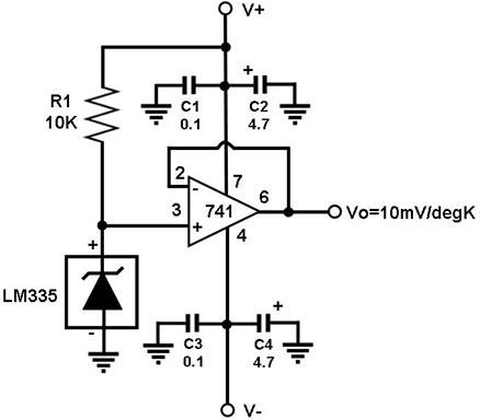
2N222 Transistor As Temperature Sensor - Simple Circuit ... This voltage is used to set operating current of the temperature-sensing 2N2222. Here is the schematic diagram of the circuit: The feedback resistor R5 is used to calibrate the output scale factor to 100mV/°C. The amplifier output is biased for zero at 0°C by the R4. So, the scale factor does not change to zero when the output is zero. Wireless Temperature Sensor with Thermistor - Circuits DIY Circuit Diagram. Working Explanation. In the first stage of this circuit that is a temperature sensor circuit is built around two 2N4401 transistors which are working as switches. A 10K thermistor is used to sense the heat. To adjust the level of heat on which you want the circuit to activate we have used a variable resistor of 20K. Temperature Indicator Circuit - ElectroSchematics.com The calibration of the temperature indicator at 100°C is done by comparing it with a precision termometer. When LM335 is at this temperature adjust P2 so you read a 1 V difference at the output of the circuit. The total current consumption is 10mA. Temperature sensor circuit diagram
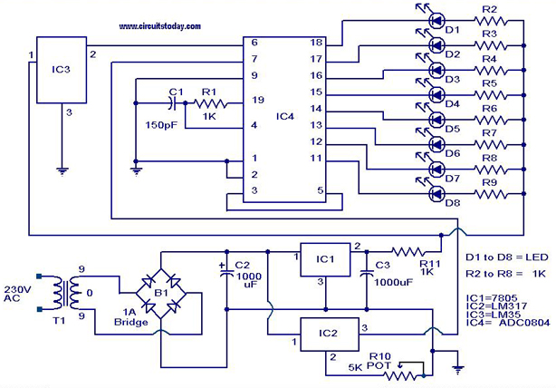
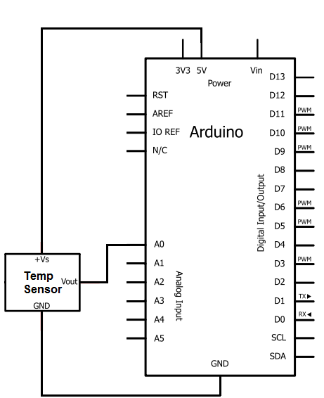
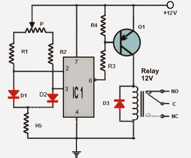
Temperature sensor circuit diagram. PDF Temperature Measurement Circuits for Embedded Applications Figure 7 provides an example of the timing diagram of the SPI serial output of the TC77 silicon IC sensor where the temperature data is represented by a 13-bit two's complement digital word. The SPI serial interface consists of the Chip Select (CS), Serial Clock (SCK) and bidirectional Serial Data (SI/O) signals. Temperature Sensor : Circuit, Types, Advantages & Its ... The circuit diagram of the relay switch using the temperature sensor is shown below. Once the circuit gets the heat then the relay will trigger the load. Any voltage can be applied to this relay like 110V AC or 220V AC or DC appliance so that we can control it routinely on the preferred temperature. This circuit is simple and cheap to build. lm35 temperature sensor working principle circuit diagram ... The circuit diagram of the Arduino LM35 Temperature Sensor is easy. Analog pin A0 used as input of the Arduino. The output pin of LM35 is connected to Analog Input A0. Join LM35 output pin to it. Apply 5 volts to Vcc pin of LM35 and ground pin. Working: Humidity and Temperature Sensor Circuit diagram Using ... The circuit is a simple circuit design that has an analog humidity and temperature sensor, Arduino Uno, and a 16x2 LCD module. The sensor can operate with a supply range from 2.4V to 5.5V. The RH pin in the sensor is for relative humidity signal while the T pin is for the temperature signal.
Temperature sensor circuit. | Download Scientific Diagram The three circuits (front-end pre-amplifier, rate-meter and temperature sensor) have been mounted in a single printed circuit board and implemented inside a NIM standard mechanical box. This choice... Heat Sensor Circuit Diagram - engineersgarage.com Pin configuration of LM35 IC is shown below. Fig. 1: Pin Configration of LM35 IC Feature of LM35 IC • It directly gives output temperature in degree Celsius so there is no need for conversion of temperature. • Operating temperature range varies from -55 to +150 degrees. • LM35 is also suitable for remote application. pt100 3 wire temperature sensor circuit diagram - Wiring ... Pt100 Rtd Sensor Pinout Features Uses Guide Datasheet 4 Wire Pt100 And 2 Pt1000 Elmb Temperature Adapter Schematic Scientific Diagram Temp 485 Pt100 2 3 And 4 Wire Rtds What Is The Difference 3 Wire Rtd Sensor Wiring A Probe Temperature Transmitter Txblock Usb Rtd S 2 3 Or 4 Wires Connection Tekon Electronics Schematic Diagram of Sensor Design. | Download Scientific ... The temperature sensor, as demonstrated in Figure 3, is composed of a ceramic multi-layer capacitor integrated with planar inductor, which forms an LC resonant circuit.
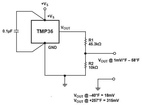
MLX90614 Infrared Temperature Sensor with Arduino, Circuit ... Read temperature without touching the object you're measuring with the MLX90614 Infrared (IR) Thermometer Sensor. Connect the two-wire interface (I2C) to your Arduino, ESP8266, ESP32, Raspberry Pi, etc. Supply voltage range is 4.5~5.5VDC. MLX90614 includes a low noise amplifier, a 17-bit ADC, and a powerful DSP module in a TO-39 through-hole ... Simple Heat Sensor or Temperature Sensor Circuit Diagram The temperature dependency of PN junctions in transistor can be understood by the formulae presented here. Base-Emitter voltage (V BE) drops approx. -2.5 mV/°C, negative sign indicates the Drop or decrease of voltage across B and E. A NPN transistor much acts like a diode if we short the Base (B) and collector (C) of Transistor. Digital Temperature Sensor Circuit Digital Temperature Sensor Circuit using 8051 Circuit Diagram Components Required AT89C51 (8051 Microcontroller) 11.0592 MHz Cystal 2 X 33pF Capacitor 10μF/16V Capacitor 3 X 10KΩ Resistor 1KΩ x 8 Resistor Pack 10KΩ POT 16X2 LCD Display ADC0804 LM35 150pF Capacitor 330Ω Resistor Power Supply Connecting Wires 8051 Programmer Circuit Design LM35 Temperature Sensor Pinout, Diagrams, Equivalents ... Power the IC by applying a regulated voltage like +5V (V S) to the input pin and connected the ground pin to the ground of the circuit. Now, you can measure the temperature in form of voltage as shown below. If the temperature is 0°C, then the output voltage will also be 0V.
Electronic Projects
6 Kinds of NTC Thermistor Temperature Measurement Circuit ... The following figure shows such a typical circuit. D-53 applied to ntc thermistor temperature measurement circuit diagram (4) D-53 is the NTC thermistor temperature sensor (temperature sensor) 25 degrees resistance 5K temperature control range 0-150 degrees DC bridge circuit application ntc thermistor temperature measurement (5)
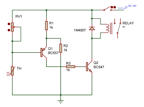
Temperature Relay controller switch Circuit - Gadgetronicx
Temperature sensing with NTC circuit (Rev. A) This temperature sensing circuit uses a resistor in series with a negative-temperature-coefficient (NTC) thermistor to form a voltage divider, which has the effect of producing an output voltage that is linear over temperature. The circuit uses an op amp in a non-inverting configuration with inverting reference to offset and
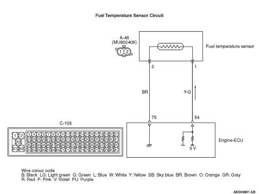
Code No. P0183: Fuel Temperature Sensor Circuit High Input
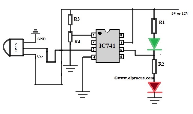
Simple Temperature Sensor Circuit using LM35 IC So, In this tutorial, we will design a simple Temperature Sensor circuit using the LM35 IC. If the temperature rises to a particular level the red Led glows which indicates the high temperature. While in other cases if the temperature falls below, the green Led glows which shows the low temperature. Hardware Components

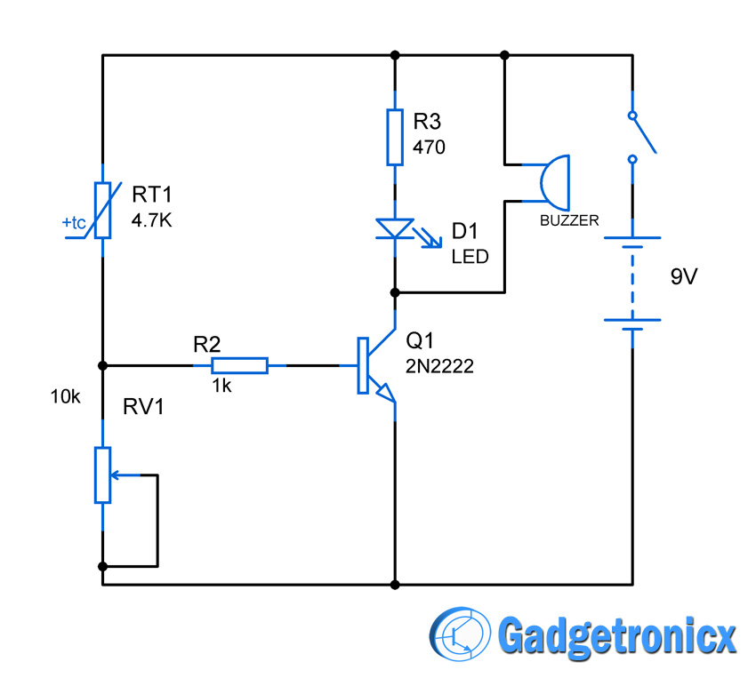
High / Over Temperature Sensor Alarm | Circuit Diagram
Arduino - Temperature Sensor | Arduino Tutorial Learn how to use temperature sensor with Arduino, how to connect DS18B20 temperature sensor to Arduino, how to program Arduino step by step. The detail instruction, code, wiring diagram, video tutorial, line-by-line code explanation are provided to help you quickly get started with Arduino. Find this and other Arduino tutorials on ArduinoGetStarted.com.

Cold Sensor Circuit
Temperature Sensor Circuit - Circuit Diagram Temperature Sensor Circuit | Circuit Diagram The schematic shown here is a project of a simple temperature sensor circuit or we can also say it a heat sensor circuit, which will activate an LED when receive heat. The circuit is easy to make and using only few components. The two BC547B transistors are connected as a darlington pair to increase
Heat sensor circuit Diagram - Gadgetronicx
Temperature sensor circuit diagrams This circuit controls very accurately a fan of any size. Just adjust the associated resistors for a different type like the R6 resistor of 100 ohm, 2 watt type and you're all set. The above circuit diagram is for a small 12 volt fan, the size and type determined by the user. Read more... Frost Alarm
Heat Sensor Circuit Diagram
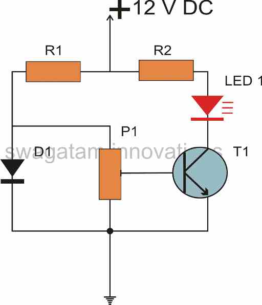
Simple temperature sensor diode 1N4148 - ElecCircuit.com Differential temperature controller circuit diagram. First, The diode sensor gets a forward-biased current. Then, there are the current flows through VR1, R1, R2, R3. We adjust VR1 to set the current, flows both diodes to be the same temperature. When both diodes get a different temperature. The voltage across them also are different.

Diagram schematic of the body temperature sensor-circuit ...
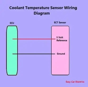
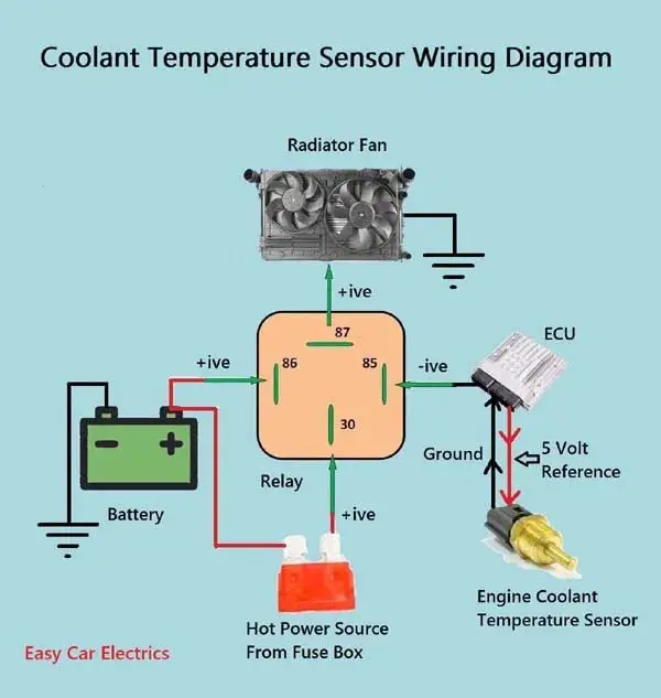
1, 2, & 3 Wire Coolant Temperature Sensor Wiring Diagram 3 Wire Coolant Temperature Sensor Wiring Diagram The two wires, a "5-volt reference", and a "ground wire" go to the ECU, and the third wire "Earth Signal Wire for Temperature Gauge" goes to the cluster-mounted temperature gauge by providing an earth signal to the temperature gauge.

MAX30205 Human Body Temperature Sensor - Maxim | Mouser
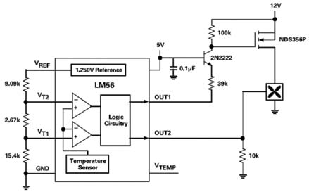
Temperature Sensor - Page 3 - Electronic Circuit Diagram March 27, 2009 Circuitguy. LM56 is a monolithic thermostat designed for simple temperature control. The chip has two programmable threshold that can be used to drive a fan and or alarm. Here is the schematic diagram of the fan control circuit: The circuit will turn on the fan when the temperature rise above 50 Celsius degree, and this threshold ...
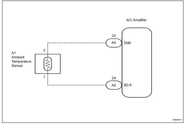
Toyota Sienna Service Manual: Ambient temperature sensor ...
Humidity Sensor - Simple Circuit Diagram Introduction. Humidity is the amount of water vapor in the air, expressed as a percentage of the maximum amount that the air could hold at the given temperature. To build a humidity sensor can be difficult because of their wide dynamic range and sensor's drive requirement. But we can build the humidity sensor with reasonable accuracy within ...
Make a Simplest Temperature Indicator Circuit - Homemade ...
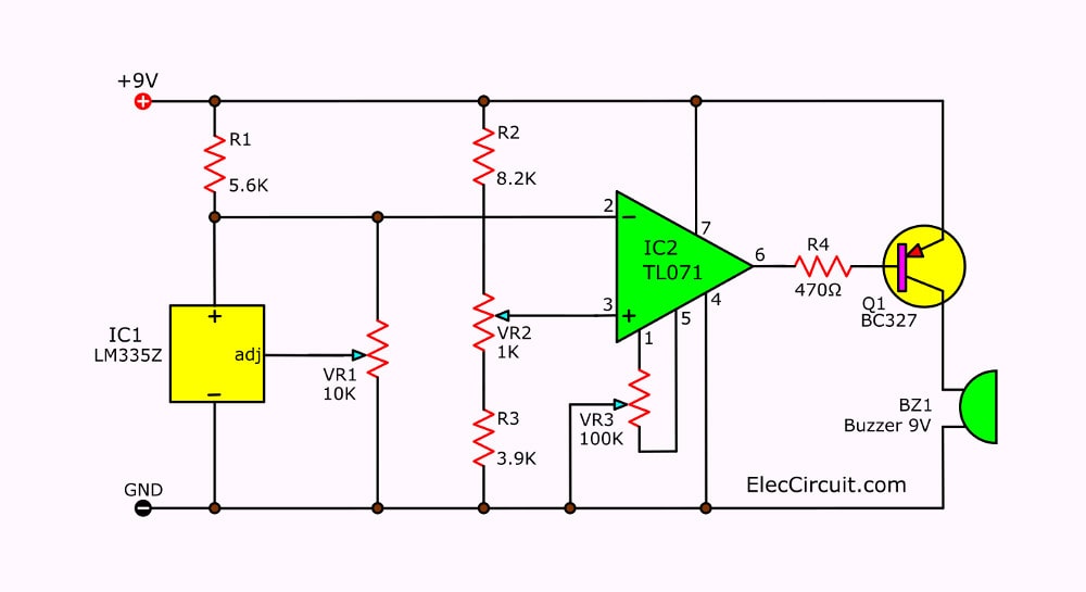
Temperature Indicator Circuit - ElectroSchematics.com The calibration of the temperature indicator at 100°C is done by comparing it with a precision termometer. When LM335 is at this temperature adjust P2 so you read a 1 V difference at the output of the circuit. The total current consumption is 10mA. Temperature sensor circuit diagram
1, 2, & 3 Wire Coolant Temperature Sensor Wiring Diagram
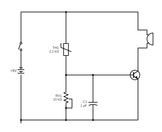
Wireless Temperature Sensor with Thermistor - Circuits DIY Circuit Diagram. Working Explanation. In the first stage of this circuit that is a temperature sensor circuit is built around two 2N4401 transistors which are working as switches. A 10K thermistor is used to sense the heat. To adjust the level of heat on which you want the circuit to activate we have used a variable resistor of 20K.

Active Versus Passive Temperature Sensors | DigiKey
2N222 Transistor As Temperature Sensor - Simple Circuit ... This voltage is used to set operating current of the temperature-sensing 2N2222. Here is the schematic diagram of the circuit: The feedback resistor R5 is used to calibrate the output scale factor to 100mV/°C. The amplifier output is biased for zero at 0°C by the R4. So, the scale factor does not change to zero when the output is zero.

Temperature Indicator Circuit

Wireless Temperature Sensor | Circuit Diagram

Temperature Sensor Circuit..Simple Heat Sensor Science Project..

Nonstop-Free Electronic Circuits Project Diagram and ...

Code No. P0117: Engine Coolant Temperature Sensor Circuit Low ...
Digital Temperature Sensor Circuit using ADC0804, LM35, and LM317
Heat Sensor Circuit And Its Working Principle

Temperature Sensor for Arduino applied for COVID 19 - Arduino ...
Temperature Detector System | Detailed Circuit Diagram Available
DS18B20 Temperature Sensor Arduino Tutorial (4 Examples)
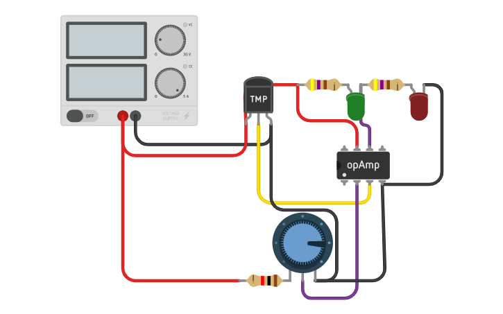
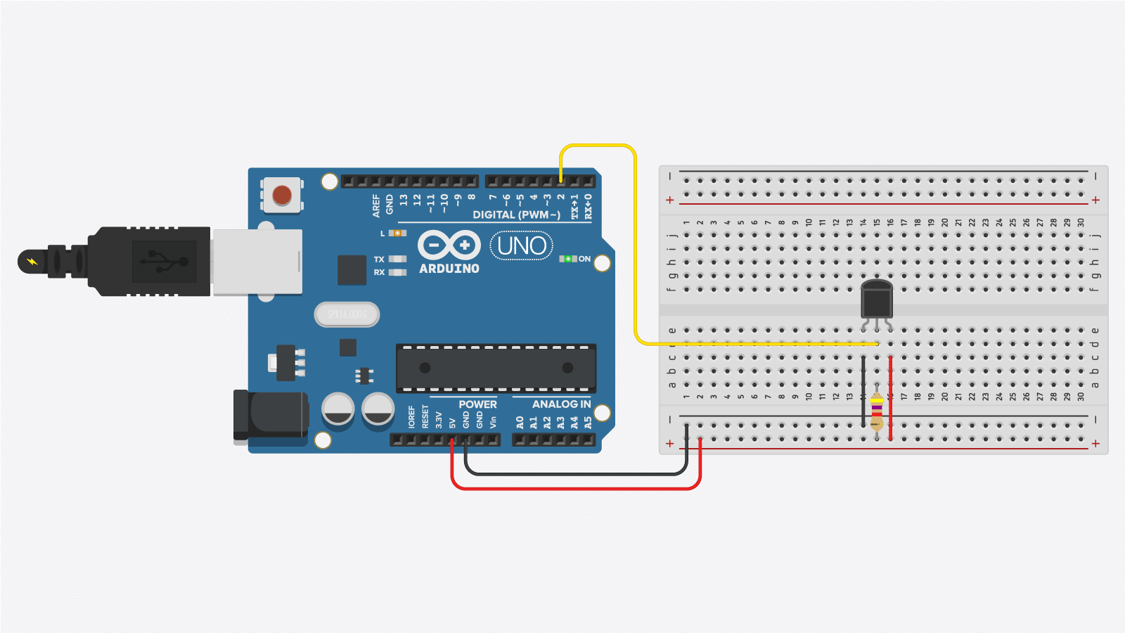
Temperature Sensor Circuit | Tinkercad
Heat Sensor Circuit And Its Working Principle

Infrared Human Body Temperature Measurement | Weixuan ...
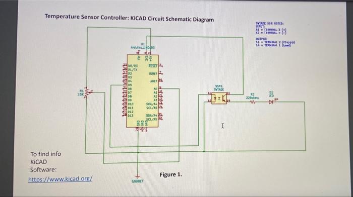
Solved Temperature Sensor Controller: KICAD Circuit | Chegg.com

Digital Temperature Sensor Circuit using 8051 & AVR ...
A Guide to Working with Temperature Sensor for Beginners

How To Make Fan Control Temperature Sensor Circuit ...

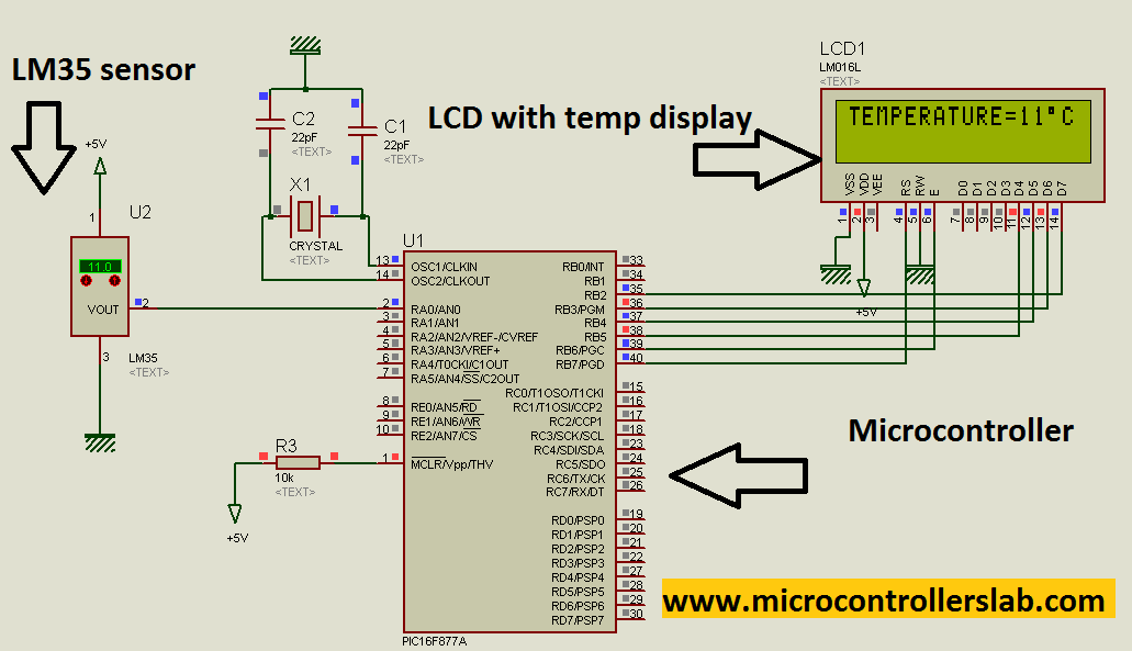
How to Integrate a Temperature Sensor Circuit to an LCD
How to Build a TMP36 Temperature Sensor Circuit
Differential Temperature Detector/Controller Circuit ...
TMP36 Temperature Sensor Pinout, Features, Equivalent ...

Applications for IC Temperature Sensors

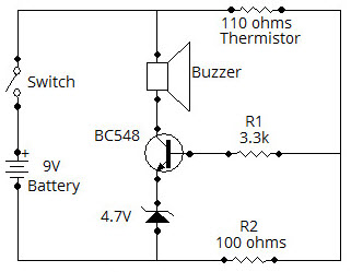
How to make Temperature sensor circuit using thermistor
temperature sensor PT100 - CircuitLab
Temperature Sensor using PIC microcontroller
3 Temperature detector circuit with buzzer alarm ...
Heat Sensor Circuit: Operation and How to Build One
1, 2, & 3 Wire Coolant Temperature Sensor Wiring Diagram

High / Over Temperature Sensor Alarm


Comments
Post a Comment