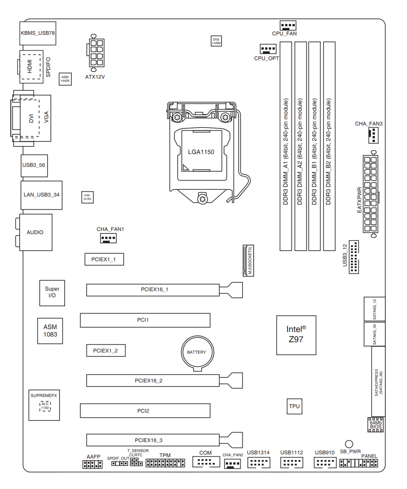
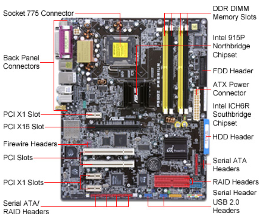
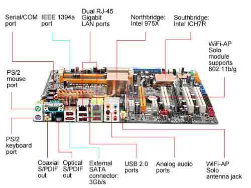
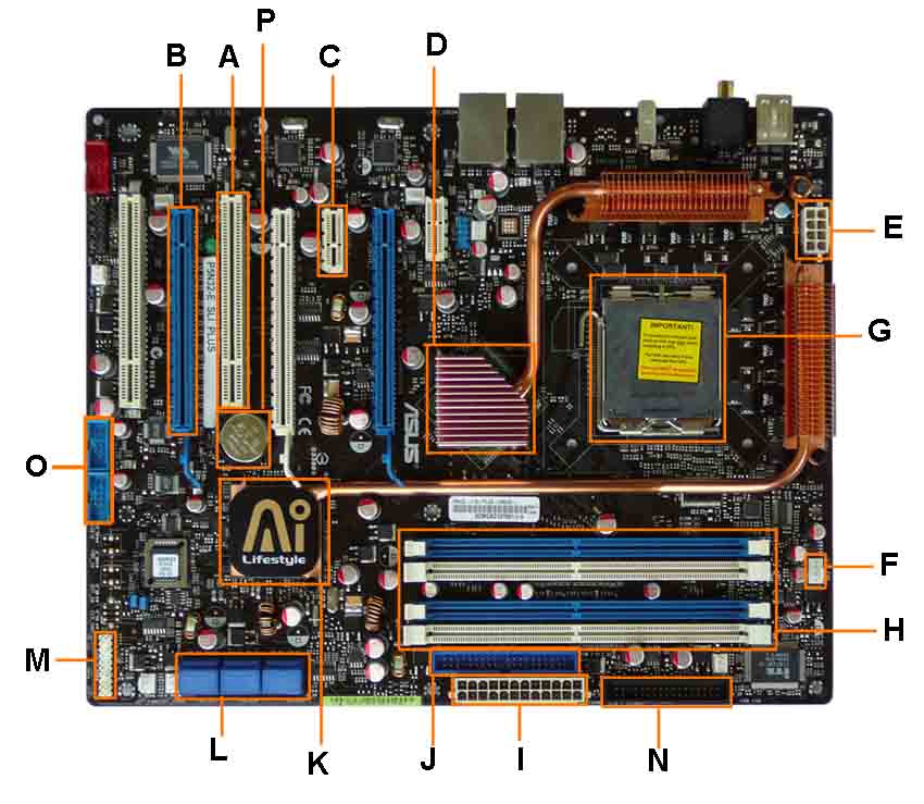
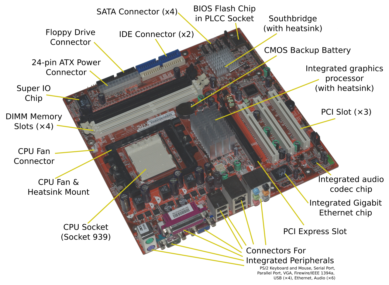
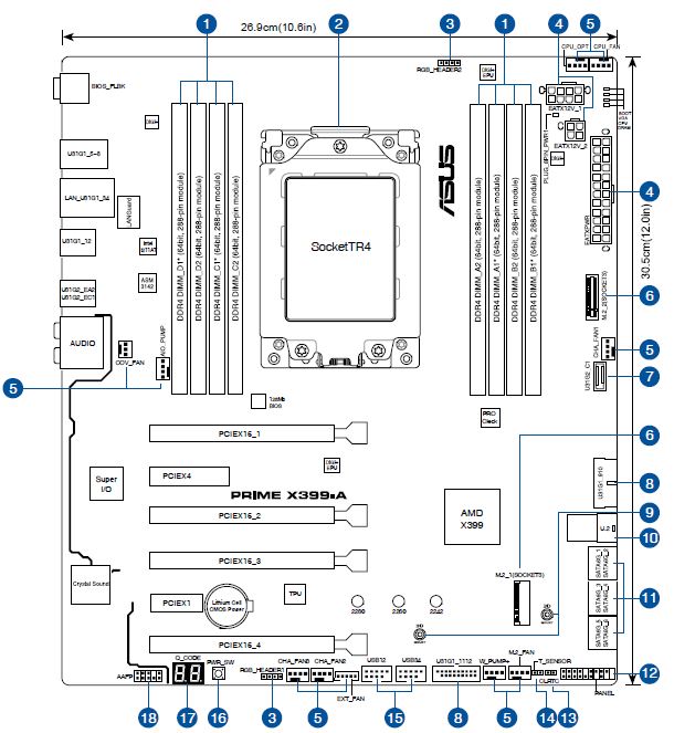
43 atx motherboard diagram with labels
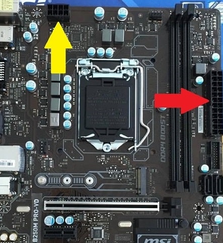
ATX Power Connector. Connects to the 24-pin ATX power cable of a power supply unit which supplies power to the motherboard. 17. mSATA Connector. Connects to a mSATA solid state drive. In most cases, this SSD is used as cache to speed up hard disk drives, but it's possible to re-purpose it as a regular hard drive. 18. Motherboard Diagram. Let's take a look at a typical higher level motherboard for an example of connector and port types. We chose the Asus Prime X470-Pro for its inclusion of many modern ...
Adapters also slightly increase the voltage drop which is something worth avoiding. It's better to first see if you can get a 24 pin cable to fit into a 20 pin motherboard before resorting to an adapter. ATX 20+4 Pin Main Power Cable Connector . Motherboards can come with either a 20 pin main power connector or a 24 pin main power connector.
Atx motherboard diagram with labels
Figure 3-58 shows a blank diagram of an ATX motherboard. Using what you learned in this chapter and in the chapter, "First Look at Computer Parts and Tools," label as many components as you can. If you would like to print the diagram, look for "Figure 3-58" in the online content that accompanies this text at www.cengagebrain.com. ATX Motherboard. Quick Installation Guide. Version 1.00 http://www.bcmcom.com. • Inspect the Package: One BC77Q Motherboard. Two SATA Cable.5 pages All of the above components are labeled in Figure 1. Figure 1: Motherboard Diagram with all components labeled. There are several components that comprise a motherboard. In this lesson, the following main components will be highlighted: System Clock; Chipset; Expansion Cards and Slots; Front Panel Connectors; Basic Input/Output System (BIOS)
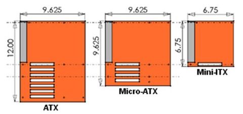
Atx motherboard diagram with labels. The standard ATX motherboard offers 7 slots at 0.8 inches (20 mm) spacing, while the microATX reduces 3 slots of 2.4 inches (61mm). Here, the width refers to the distance along the external connector edge, while the depth refers to distance from front to rear. Note: There once was a Mini ATX with a design of 5.9 × 5.9 in (15 × 15 cm). As the form factor of motherboard as a series of versions of the MOBO from AT, ATX, BTX, LPX, and NLPX .Compatible words being broadcast, that's why it is the MOBO will synchronized the speed of processor, RAM, and Video Card(VGA).Unlike only if the MOBO is built-in through the Input/Output ports. Functions: 1. I Googled: atx motherboard labeled diagram...and about the 4th entry down has a Cengage Learning .pdf about labeling ATX motherboards. But even that isn't exactly the same. There must be something in the chapter hints at which of the 100's of different ATX motherboard component layouts, you happen to be working with. Install a network adapters as follows:On the Shelf, expand Network Adapters.Select a network adapter.Select Details to evaluate each component.Identify the possible network adapters that will fit into the motherboard.Repeat steps 2b-2d for each network adapter.From the Shelf, drag the correct network adapter to the correct slot on the motherboard for Computer 1.From the Shelf, drag the correct network adapter to the correct slot on the motherboard for Computer 2.
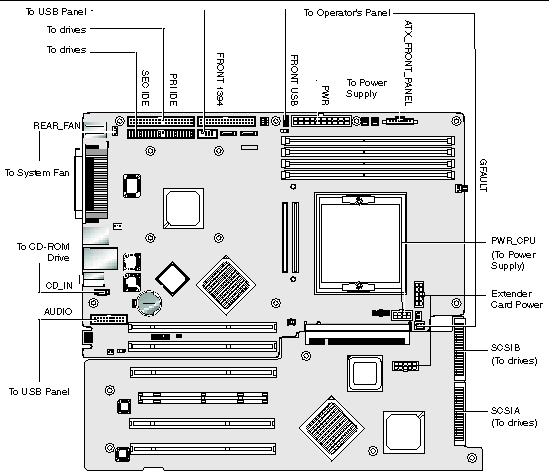
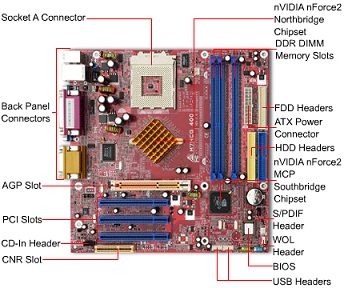
"mother" board in relation to these. A PC motherboard generally has a series of slots, allowing daughter boards to be plugged in directly. Other connectors on the motherboard allow communication through cables with various peripheral devices, both inside and outside the compu ter case. ATX motherboard legend 1. Processor socket 2. Chipset 3 ... We'll begin our breakdown by using a typical ATX motherboard. The image below corresponds to an Asus Z97-Pro Gamer and its appearance, features, and functions can be found in dozens more like it. JPWR1~2: ATX Power Connectors These connectors allow you to connect an ATX power supply. To connect the ATX power supply, align the power supply cable with the connector and firmly press the cable into the connector. If done correctly, the clip on the power cable should be hooked on the motherboard's power connector. 3 V 3 V V V d d # V d d d ... Atx is the de facto standard and offers the most space for features and expansion. Is a chip that acts as an interface between the main memory the cpu and other components has a large heat sink on top of it. Motherboard diagram with labels. The vast majority of todays consumer motherboards come in one of three sizes.
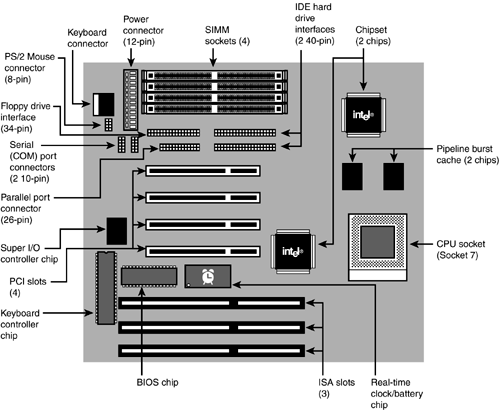
View Labeling a Motherboard.docx from CIS MISC at Amarillo College. Labeling the Motherboard This figure shows a diagram of an ATX motherboard. Label as many of the 19 components as you can. Start Use the above diagram to match the case type labels on the left with their corresponding cases, identified by letters, on the right. A. Mini-ITX Tower B. Micro-ATX Tower C. Micro-ATX Tower D. ATX Mid-Tower E. ATX Full-Tower ATX combines the best functionality from the form factors that dominated the computer industry in the early 1990s: the high integration of LPX and the expandability of Baby-AT. The ATX form factor is essentially a Baby AT motherboard rotated 90 degrees within the chassis enclosure and providing a new mounting configuration for the power supply. CPU socket, DIMM, PCIe x16, Northbridge, Southbridge, PCI, SATA, Battery, Analog Audio I/O, USB, 4 pin 12V CPU Power connector, PS2 ports, 24 pin ATX Power connection ...
Figure 3-58 shows a blank diagram of an ATX motherboard. Using what you learned in this chapter and in the chapter, "First Look at Computer Parts and Tools," label as many components as you can. If you would like to print the diagram, look for "Figure 3-58" in the online content that accompanies this text at www.cengagebrain.com.
The motherboard does not work well or you can not get it work according to user guide. The motherboard has been dropped and damaged. The motherboard has obvious sign of breakage. ∙ ∙Do not leave this motherboard in an environment above 60°C (140°F), it may damage the motherboard.
ATX MOTHERBOARD DIAGRAM . A. Parallel/Serial Port B. USB Ports C. PS/2 Connector D. ATX Power Socket E. CPU Slot 1 F. Northbridge Chipset G. DIMM Slots H. Primary and Secondary IDE Controller I. Floppy Drive Controller J. CMOS Battery Holder K.Southbridge Chipset L. ISA Slot M. PCI Slot N. AGP Slot O. ROM/BIOS Chipset
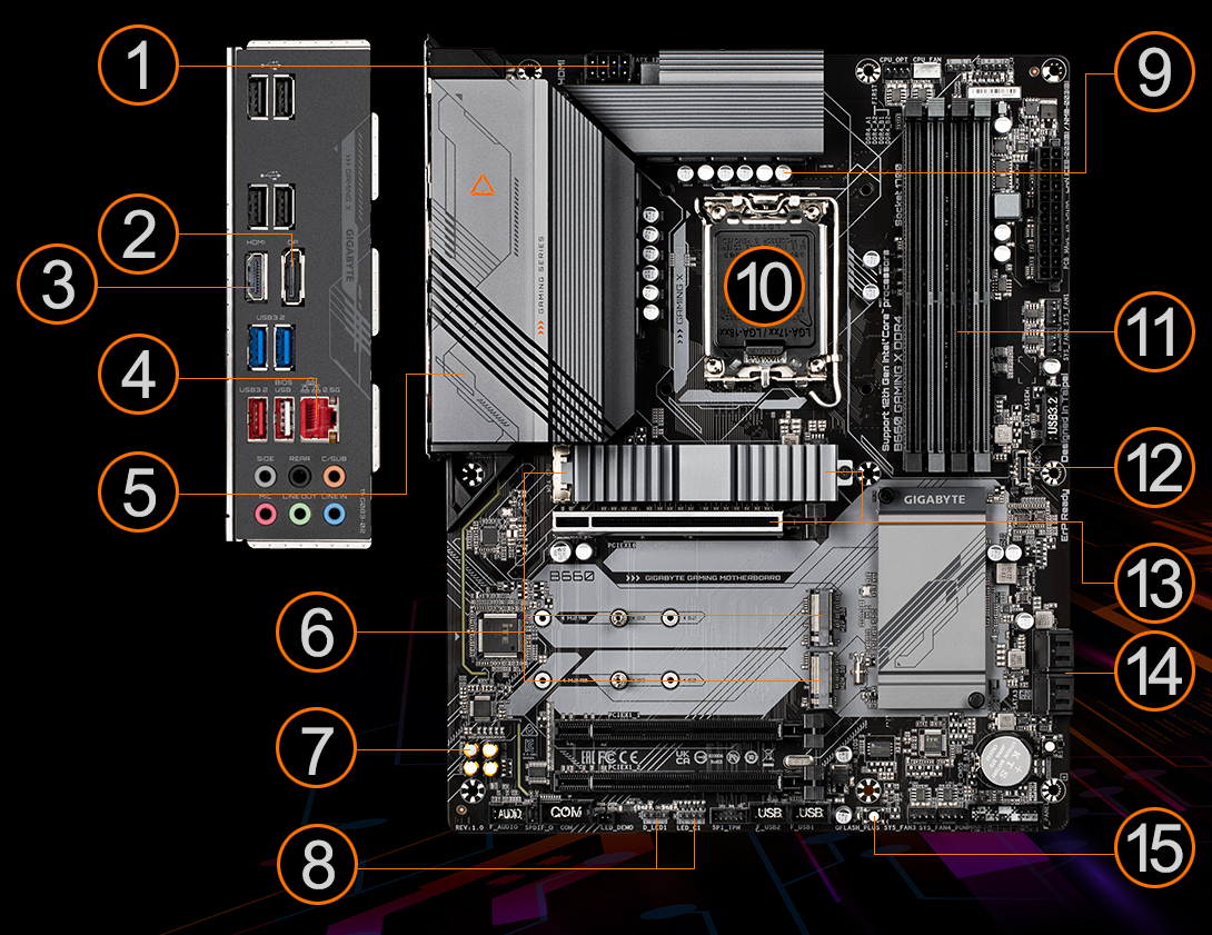
Motherboard Internal Diagram-Front ATX 19V Power Connector Intel LGA1151 CPU Socket Intel H110 Chipset PCI Express x1 slot SATAIII Ports (SATA1/2) Front Panel Audio Header Front Panel Header CPUFAN Connector RJ-45 LAN Port USB 3.0 Ports 19V DC Power-in Jack Display Port HDMI Port Line-OUT MIC-IN Speaker Connector USB 2.0 Header
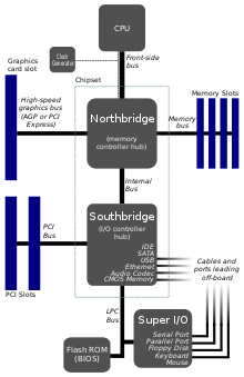
Download Ebook Schematic Block Diagram Of Atx Motherboard GNSR 2001 Insulated Gate Bipolar Transistor IGBT Theory and Design Presents information on getting the most out of a PC's hardware and software, covering such topics as upgrading the BIOS, configuring the hard drive, installing more RAM, improving CPU performance, and adding COM ports.
All of the above components are labeled in Figure 1. Figure 1: Motherboard Diagram with all components labeled. There are several components that comprise a motherboard. In this lesson, the following main components will be highlighted: System Clock; Chipset; Expansion Cards and Slots; Front Panel Connectors; Basic Input/Output System (BIOS)
ATX Motherboard. Quick Installation Guide. Version 1.00 http://www.bcmcom.com. • Inspect the Package: One BC77Q Motherboard. Two SATA Cable.5 pages
Figure 3-58 shows a blank diagram of an ATX motherboard. Using what you learned in this chapter and in the chapter, "First Look at Computer Parts and Tools," label as many components as you can. If you would like to print the diagram, look for "Figure 3-58" in the online content that accompanies this text at www.cengagebrain.com.














Comments
Post a Comment