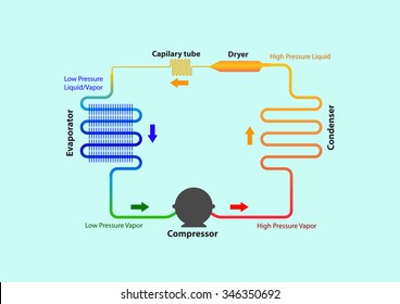
43 vapour compression cycle diagram
the p-h and t-s diagram for the simple vapor compression refrigeration cycle is shown in the figure for vapour entering the compressor is in dry saturation condition the dry and saturated vapour entering the compressor at point 1 that vapour compresses isentropic ally from point 1 to 2 which increases the pressure from evaporator pressure to … Vapour compression heat pumps use a 'refrigerant' to transfer heat and his hence similar to an air conditioning unit. This diagram also illustrates how easy it is to utilise the key components but to reverse the process i.e. to pump heat out rather than in, thus becoming an 'air conditioning' unit (more correctly called a cooling unit).
T-s diagram for a vapour compression refrigeration cycle when the refrigerant leaves the evaporator as (a) saturated vapour (b) superheated vapour . Gas refrigeration cycle (a) Schematic diagram (b) T-s diagram . The simplest gas refrigeration cycle is the reversed Brayton cycle . Processes: - 1-2: isentropic compression for state 1 ...
Vapour compression cycle diagram
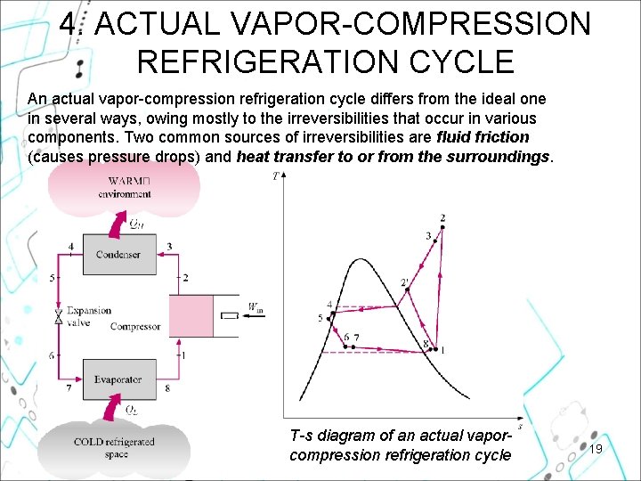
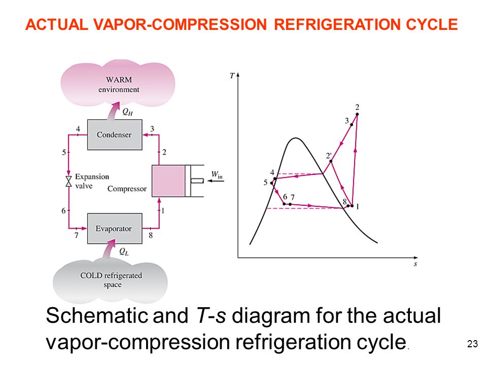
In order to properly understand this diagram, it is best to go through the vapor compression cycle on a P-H diagram. Understanding the P-H Diagram. On the P-H diagram, pressure is indicated on the y-axis and enthalpy is indicated on the x-axis. Typically enthalpy is in units of Btu/lb and pressure is in units of pounds per square inch (psi). Actual Vapor‐Compression Refrigeration Cycle Fig. 5-4: T-s diagram for actual vapor-compression cycle. Most of the differences between the ideal and the actual cycles are because of the irreversibilities in various components which are: 1-In practice, the refrigerant enters the compressor at state 1, slightly superheated vapor, instead of ... The basic difference between vapour compression and vapour absorption cycles will thus be to replace the compressor of the vapour compression cycle by a set of equipment which fulfils the objective discussed above. The other important element i.e., condenser, expansion device and evaporator will exist in both systems. Simple Vapour Absorption ...
Vapour compression cycle diagram. This is represented by the process 1-2 in the T-s diagram given above. It is an Isentropic compression process of the refrigerant where work is supplied to the compressor to increase the pressure. If the refrigerant is found in both liquid and vapour form at this stage, it is called wet compression. Homework Equations N/A The Attempt at a Solution I am trying to understand the above ph diagram (for a vapour compression cycle), In some examples, point 1 is situated as above in the image (i.e. to the right of the saturated vapour line) and at other times it's situated exactly where I drew the purple arrow (i.e. on the saturated vapour line). 4.5. Actual vapour compression cycle Fig. 19. T-S diagram for actual Vapour Compression cycle. The actual vapour compression cycle is different from the theoretical vapour compression cycle in many ways. The main deviations between the theoretical and actual cycle are: (1) Vapour refrigerant leaving the evaporator is in superheated state. Cycle with dry saturated vapour after compression 2. Cycle with wet vapour after compression 3. Cycle with superheated vapour after compression 4. Cycle with superheated vapour before compression 5. Cycle with sub-cooling of refrigerant Read : COP of Air Refrigerator working on reversed Carnot cycle with PV and Ts Diagram
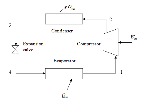
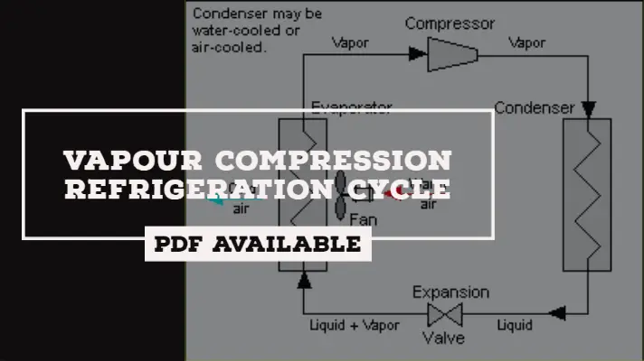
Introduction Simple Vapor Compression Refrigeration system, Analysis of vapor compression cycle, Use of T-s and P- h charts, Effect of change in suction and discharge pressures on C.O.P Effect of sub cooling of condensate & superheating of refrigerant vapor on C.O.P of the cycle, Actual vapor compression refrigeration cycle Welcome to Engineering Solutionswith Akshay In this video we will come across the schematic representation and working of Vapour Compression Refrigeration Cy... The vapor-compression refrigeration cycle has four components: evaporator, compressor, condenser, and expansion (or throttle) valve. The most widely used refrigeration cycle is the vapor-compression refrigeration cycle. In an ideal vapor-compression refrigeration cycle, the refrigerant enters the compressor as a saturated vapor and is cooled to ... Vapour after Compression A vapour compression cycle with dry saturated vapour after compression is shown on T-s diagrams in Figures 2.2(a) and (b) respectively. At point 1, let T 1, p 1 and s 1 be the temperature, pressure and entropy of the vapour refrigerant respectively. The four processes of the cycle are as follows : (a) T-s Diagram (b) p ...
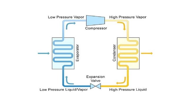
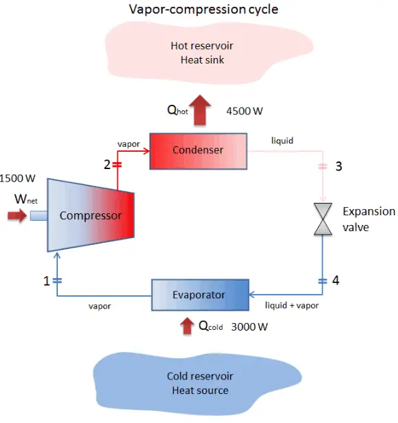
Vapor-compression cycle - Thermodynamic cycle of heat pumps. The vapor-compression uses a circulating liquid refrigerant as the medium (usually R134a) which absorbs and removes heat from the space to be cooled and subsequently rejects that heat elsewhere. The figure depicts a typical, single-stage vapor-compression system. Carnot Vapour Cycle Processes. The cycle is completed by the following four processes: 1-2 Process (Isothermal Expansion) 2-3 Process (Adiabatic Expansion) 3-4 Process (Isothermal Compression) 4-1 Process (Adiabatic Compression) Read also: Carnot Cycle: Principle Processes, Efficiency with [P-v and T-s Diagram] 1. Explanation, Components & Diagram. Vapour compression refrigeration system runs on 'vapour compression cycle', in which, a suitable working substance, termed as 'refrigerant', is used. For example: Freon compounds such as R-1, R-12, R-22 etc. Carbon dioxide (C0 2 ), Ammonia (R-717) and Water (R-718) are also used as refrigerants in some ... The refrigeration cycle is the main basic cycle for all air conditioning and refrigeration equipment. In this chapter, we will discuss, basics of a refrigeration cycle, mainly vapor compression cycle, main concept, parts, components, working principle along with a real example, etc.
Solved Consider A Vapor Compression Refrigeration Cycle Using R 1 Chegg Com
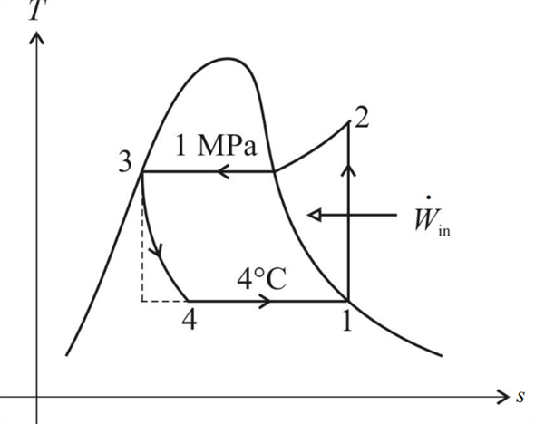
Figure 2: Temperature-Entropy diagram The thermodynamics of the vapor compression cycle can be analyzed on a temperature versus entropy diagram as depicted in Figure 2. At point 1 in the diagram, the circulating refrigerant enters the compressor as a saturated vapor.

Vapor Compression Refrigeration Wikipedia
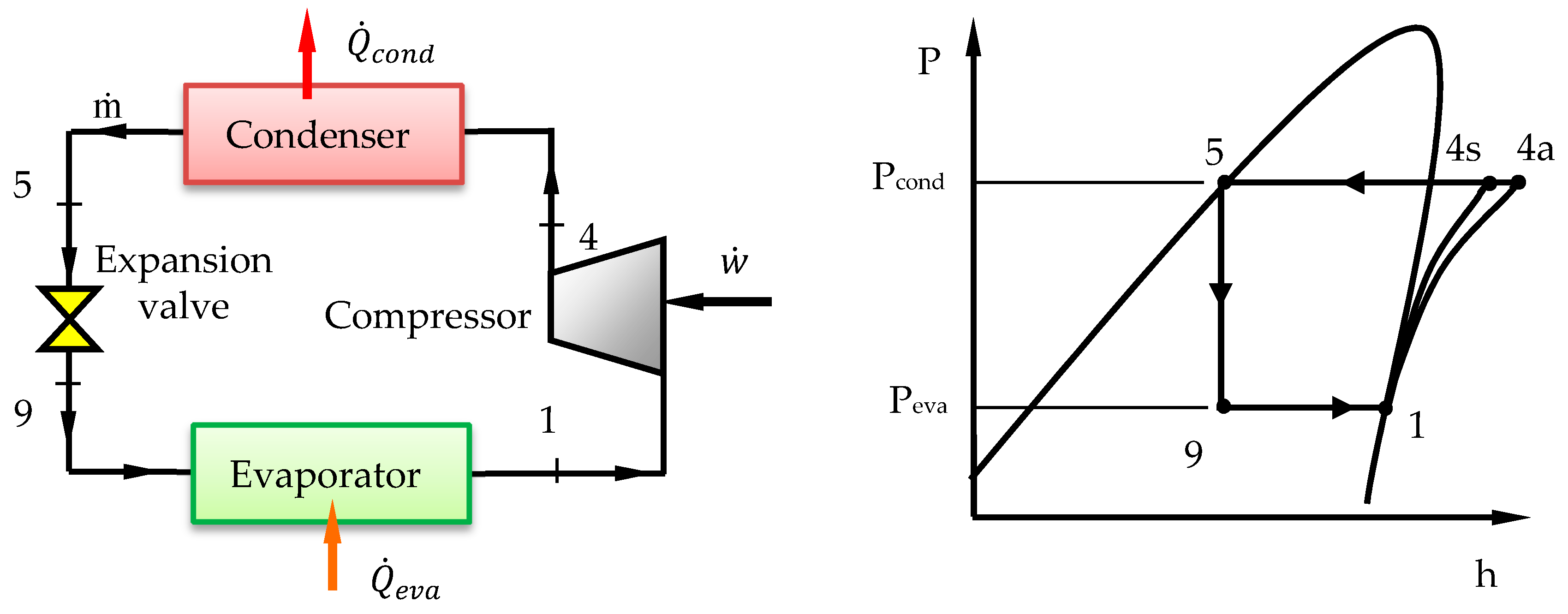
Simple Vapour Compression Cycle on P-h Chart: A simple vapour compression cycle is shown by 1—2—3—4—1 on P-h chart of Fig. 36.24. 1- 2 Isentropic compression in compressor. 2- 3 Constant pressure cooling (Heat rejection). 3- 4 Isenthalpic expansion through expansion valve. 4- 1 Constant pressure heat absorption.

P H Diagram Of Vapor Compression Refrigeration Cycle Generally The Download Scientific Diagram
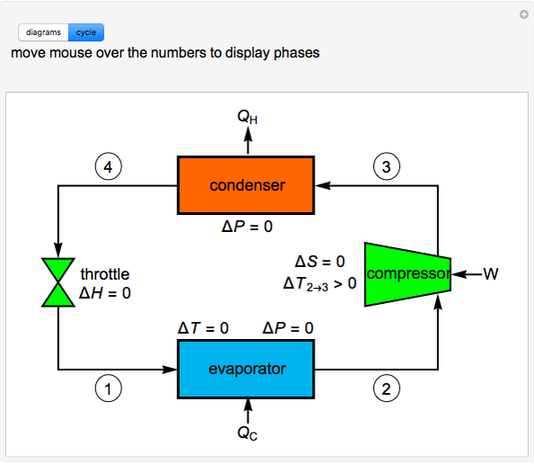
The Vapor Compression Refrigeration Cycle involves four components: compressor, condenser, expansion valve/throttle valve and evaporator. It is a compression process, whose aim is to raise the refrigerant pressure, as it flows from an evaporator.

A Vapor Compression Refrigeration System Circulates Refrigerant 134a At A Rate Of 6kg Min The Refrigerant Enters The Compressor At 10 O C 1 4 Bar And Exits At 7 Bar The Isentropic Compressor
Vapor Compression Cycle -Working Diagram A refrigeration system can also be used as a heat pump, in which the useful output is the high-temperature heat rejected at the condenser. Alternatively, a refrigeration system can be used for providing cooling in summer and heating in winter. Such systems have been built and are available now
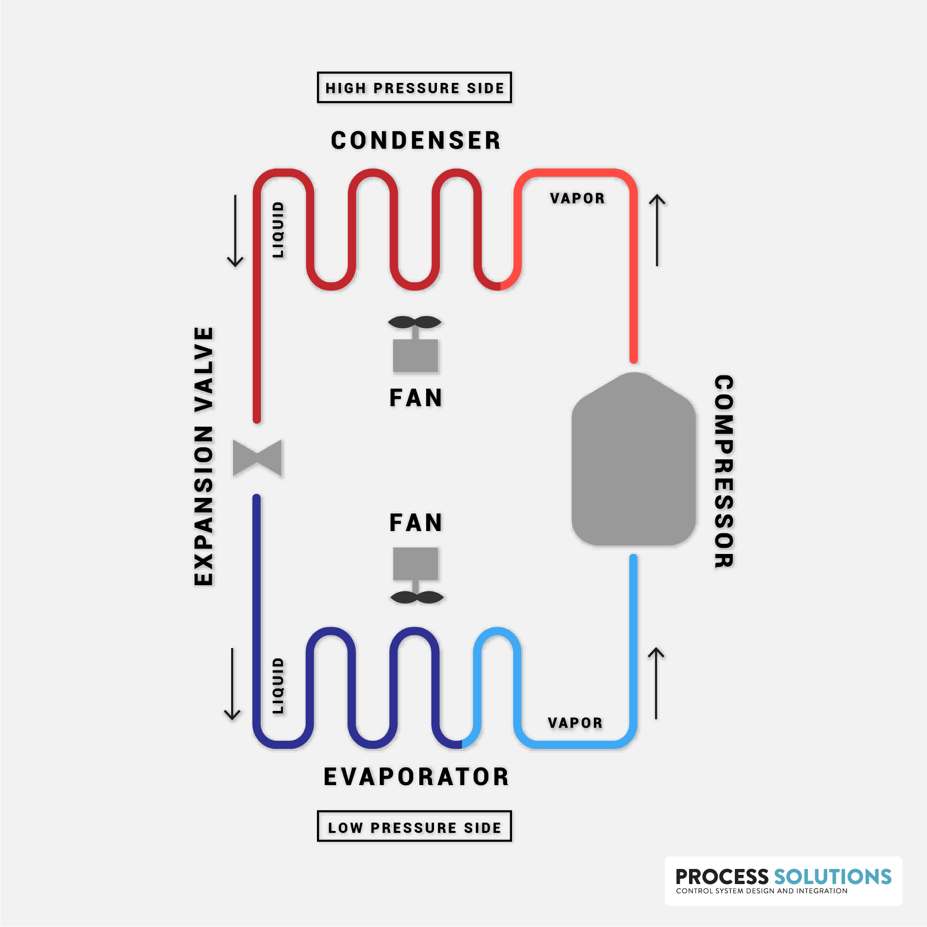
How Does A Compression Refrigeration System Work Process Solutions Inc
P-H and T-S Diagrams of vapour compression cycle Explanation: The dry saturated vapour enters the compressor, this is shown as point 1 in the chart above. This compressor increases the pressure of the dry saturated vapour from the evaporator pressure to condenser pressure. During the compression, the dry saturated vapour's temperature increases.

Draw A Neat Sketch Of Vapour Compression Refrigeration Cycle Describe Its Working Mechanical Engg Diploma Simple Notes Solved Papers And Videos
Temperature-entropy diagram for ideal vapour compression cycle. Expansion is a constant enthalpy process, shown as a vertical line on the P-h diagram. No heat is absorbed or rejected during this expansion, the liquid just passes through a valve.

Vapor Compression Refrigeration Cycle Interactive Simulation Youtube
Here are two diagrams of the vapour compression cycle. Try your mouse over the diagrams to commence the activatation of each process in turn. The four processes are Vaporization (Evaporation), Compression, Condensation and Expansion.
The 4 Main Refrigeration Cycle Components The Super Blog
The T-s diagram for a vapor-compression refrigeration cycle is shown below. Figure 1: Vapor-Compression Refrigeration Cycle T-s diagram Below is a possible CyclePad design of a refrigeration cycle. The layout shown below is a clickable image.

Vapour Compression Refrigeration System Theteche Com
Vapour compression cycle generally known as VCC is a refrigeration cycle. In this cycle, the refrigerant is sealed condition in an airtight mechanism is compressed in a compressor which permits the transfer of heat energy. The refrigerant absorbs heat from one place and releases it to another place.
Solved An Ideal Vapor Compression Refrigeration Cycle That Uses R Chegg Com
Vapour Compression Refrigeration Cycle is the most widely used refrigeration system. In this system, the working fluid is a vapor. It readily evaporates and condenses or changes alternatively between the vapor and liquid phase without leaving the refrigerating plant. During evaporation, it absorbs heat from the cold body and this heat is used ...

Refrigeration Process Refrigerant Vapor Compression Cycle Bright Hub Engineering
P-h diagram of vapor compression refrigeration cycle Generally, the vapor compression refrigeration system consists of a condenser, an expansion valve, an evaporator, and a compressor. The vapor ...

Schmatic And T S Diagram For Actual Vapor Compression Refrigeration Cycle
The basic difference between vapour compression and vapour absorption cycles will thus be to replace the compressor of the vapour compression cycle by a set of equipment which fulfils the objective discussed above. The other important element i.e., condenser, expansion device and evaporator will exist in both systems. Simple Vapour Absorption ...
What Is The H S Diagram For Vapour Compression Refrigeration Cycle Quora
Actual Vapor‐Compression Refrigeration Cycle Fig. 5-4: T-s diagram for actual vapor-compression cycle. Most of the differences between the ideal and the actual cycles are because of the irreversibilities in various components which are: 1-In practice, the refrigerant enters the compressor at state 1, slightly superheated vapor, instead of ...

Schematic Diagram Of A Typical Vapor Compression Refrigeration Cycle 17 Download Scientific Diagram
In order to properly understand this diagram, it is best to go through the vapor compression cycle on a P-H diagram. Understanding the P-H Diagram. On the P-H diagram, pressure is indicated on the y-axis and enthalpy is indicated on the x-axis. Typically enthalpy is in units of Btu/lb and pressure is in units of pounds per square inch (psi).
Refrigeration Cycle Images Stock Photos Vectors Shutterstock

Refrigeration Cycles Chapter 11 Ert 206 4 Thermodynamics Ppt Video Online Download

Vapor Compression Refrigeration System Basic Working Parts Of System
Vapour Compression Refrigeration Cycle Components Working Process Applications Pdf

New Refrigerants And System Configurations For Vapor Compression Refrigeration
Design Of Vapor Compression Refrigeration Cycles
Resources Saylor Org

T S Diagram Of The Vapour Compression Refrigeration Cycle Considered In Download Scientific Diagram
Processes Free Full Text Performance Analysis And Working Fluid Selection For Single And Two Stages Vapor Compression Refrigeration Cycles Html
Ph Diagram For A Vapour Compression Cycle Physics Forums
Vapor Compression Refrigeration System Environmental Resources Engineering

Ch10 Lesson B Page 2 The Ideal Vapor Compression Refrigeration Cycle

Comparison Of Actual And Theoretical Vapor Compression Cycle

Actual Vapour Compression Cycle And The Effect Of Suction And Discharge Pressure And Problems
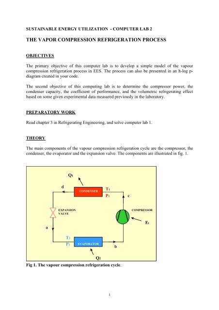
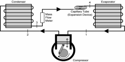
The Vapor Compression Refrigeration Process Kth

Thermodynamic Calculations Of Two Stage Vapor Compression Refrigeration Cycle With Flash Chamber And Separate Vapor Mixing Intercooler Application Center
Vapor Compression Refrigeration

Vapour Compression Cycle Definite Guide With Video Diagram
Chapter 11 Refrigeration Cycles 1 Outline Refrigerators And

B Draw T S P H Diagrams Of Vapour Compression Refrigeration System Homeworklib

Theoretical Vapour Compression Cycle Automobile
What Is Vapor Compression Cycle Refrigeration Cycle Definition

Ideal Vapour Compression Refrigeration Cycle In 2021 Interview Questions Interview Questions And Answers Vapor

Vapor Compression Refrigeration Wikipedia

Simple Practical Cycle Understanding Refrigeration
5 Vapour Compression Cycle On Ph And T S Diagrams Lessons Blendspace

Vapour Compression Refrigeration Cycle It S Schematic And T S P H Diagram Youtube

Vapour Compression Cycle Definite Guide With Video Diagram
Ordinary Vapor Compression Ovc Cycle For Refrigerant R 134a Wolfram Demonstrations Project


The vapour compression refrigeration cycle is the backbone of modern cooling and heat pump systems. At INS3 we simplify these complex engineering concepts with clear diagrams and practical insights, helping learners and professionals understand refrigeration processes better.
ReplyDelete