41 how to wire a shunt trip breaker wiring diagram
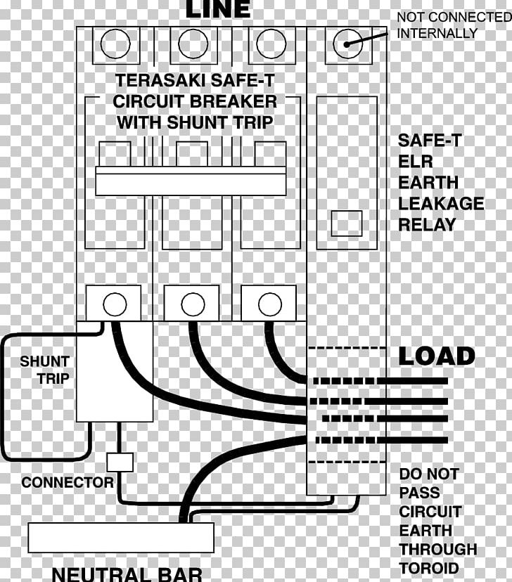
Resolution: Connect the appropriate voltage (ie. 120V to 240V for the -1021 suffix) to the two terminals on the shunt trip. Land the switch leg ... Phase Controller Wiring / Phase Failure Relay Diagram. When we talk about the 3 phase power wiring or designing or installation a three phase electrical panel ...
25 Apr 2017 — Connect power to the circuit on which the shunt-trip breaker is installed and test the shunt trip operation. Close the circuit breaker manually.

How to wire a shunt trip breaker wiring diagram
1-1 Shunt Trip Installed in Q-Frame Circuit Breaker ... Before attempting to install the shunt trip, check that ... Fig. 2-6. Shunt Trip Connection Diagram ...8 pages 13 Aug 2020 — Shunt trip coil is energized only for a short time, over time to burn; so in the control loop in the normally closed contacts connected in ... 1 Aug 2021 — A shunt trip breaker is a specially designed circuit to trip the MCCB manually by the applied a power supply to its shunt trip coil. The main ...
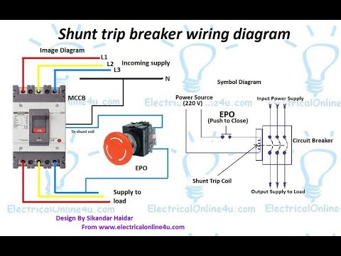
How to wire a shunt trip breaker wiring diagram. 13 Mar 2019 — Shunt trip breaker wiring diagram, This post is about the single wiring diagram of MCCB shunt trip breaker. In the diagram an MCCB (molded ... 1 Aug 2021 — A shunt trip breaker is a specially designed circuit to trip the MCCB manually by the applied a power supply to its shunt trip coil. The main ... 13 Aug 2020 — Shunt trip coil is energized only for a short time, over time to burn; so in the control loop in the normally closed contacts connected in ... 1-1 Shunt Trip Installed in Q-Frame Circuit Breaker ... Before attempting to install the shunt trip, check that ... Fig. 2-6. Shunt Trip Connection Diagram ...8 pages
20 Most Recent Square D Qo250gfi 2pole 50amp 240v Questions Answers Fixya
2
Shunt Trip Breaker Wiring Diagram In Urdu Hindi How To Install A Shunt Trip Breaker Youtube
Ansul Wiring Check Electrician Talk
2

Madcomics Shunt Trip Breaker Wiring

Shunt Trip Breaker Wiring Diagram In Urdu Hindi How To Install A Shunt Trip Breaker Youtube

Eaton Br120st Plug On Breakers Shunt Trip Circuit Power Distribution Platt Electric Supply

B12000s01 Siemens Circuit Breaker Mag Trol Distributors Inc
How To Wire A Shunt Trip Breaker Wiring Diagram Diy Guide
1
How To Wire A Shunt Trip Breaker Wiring Diagram Diy Guide

Qob2701021 Square D 2 Pole 70 Amp Circuit Breaker With Shunt Trip

Siemens 20 Amp 1 Pole 10 Ka Type Qp With Shunt Trip Circuit Breaker Q12000s01 The Home Depot
Ch160st Eaton Ch Thermal Magnetic Circuit Breaker Eaton

Madcomics Shunt Trip Breaker Wiring

How To Shut Off Intake Fan Using Ansul System

Solved I Have A Three Pole Type Bl 70 Amp Shunt Trip Fixya

Shunt Trip With Multiple Push Button Mike Holt S Forum
1

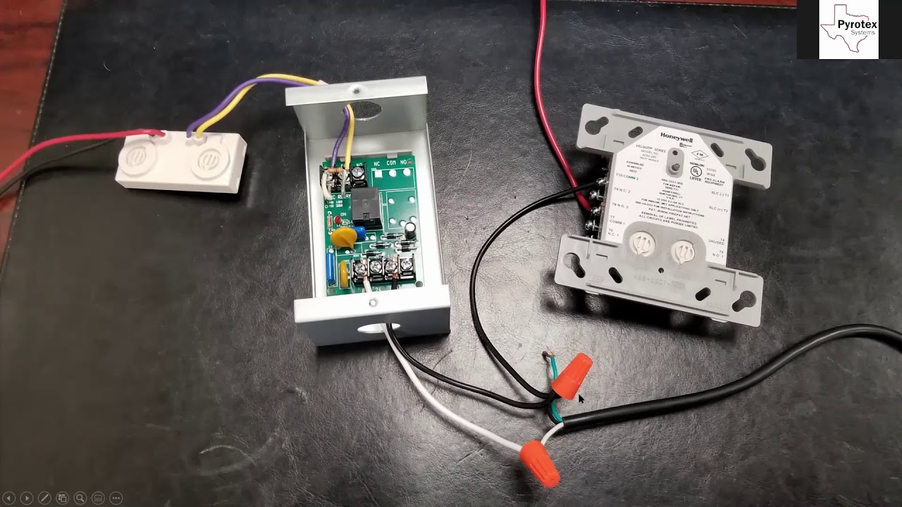
How To Wire Elevator Shunt Trip Fire Alarms Online
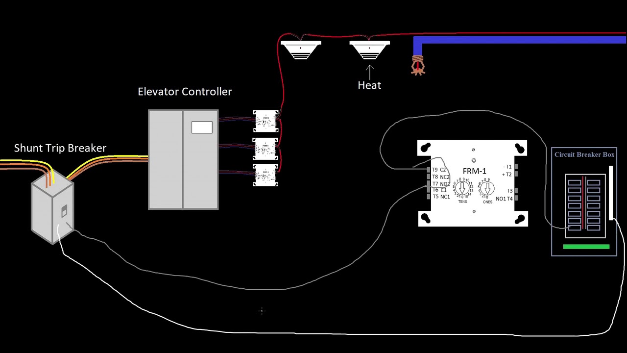
39 Elevator Shunt Trip Introduction To Fire Alarms Youtube

Kyaw Thulatt Kyawthulatt85 Profile Pinterest

Br120st Eaton Type Br Brkr 20a 1 Pole 120 240v 10k W Shunt Trip
2

Shunt Trips Shunt Trip Circuit Breakers Relectric
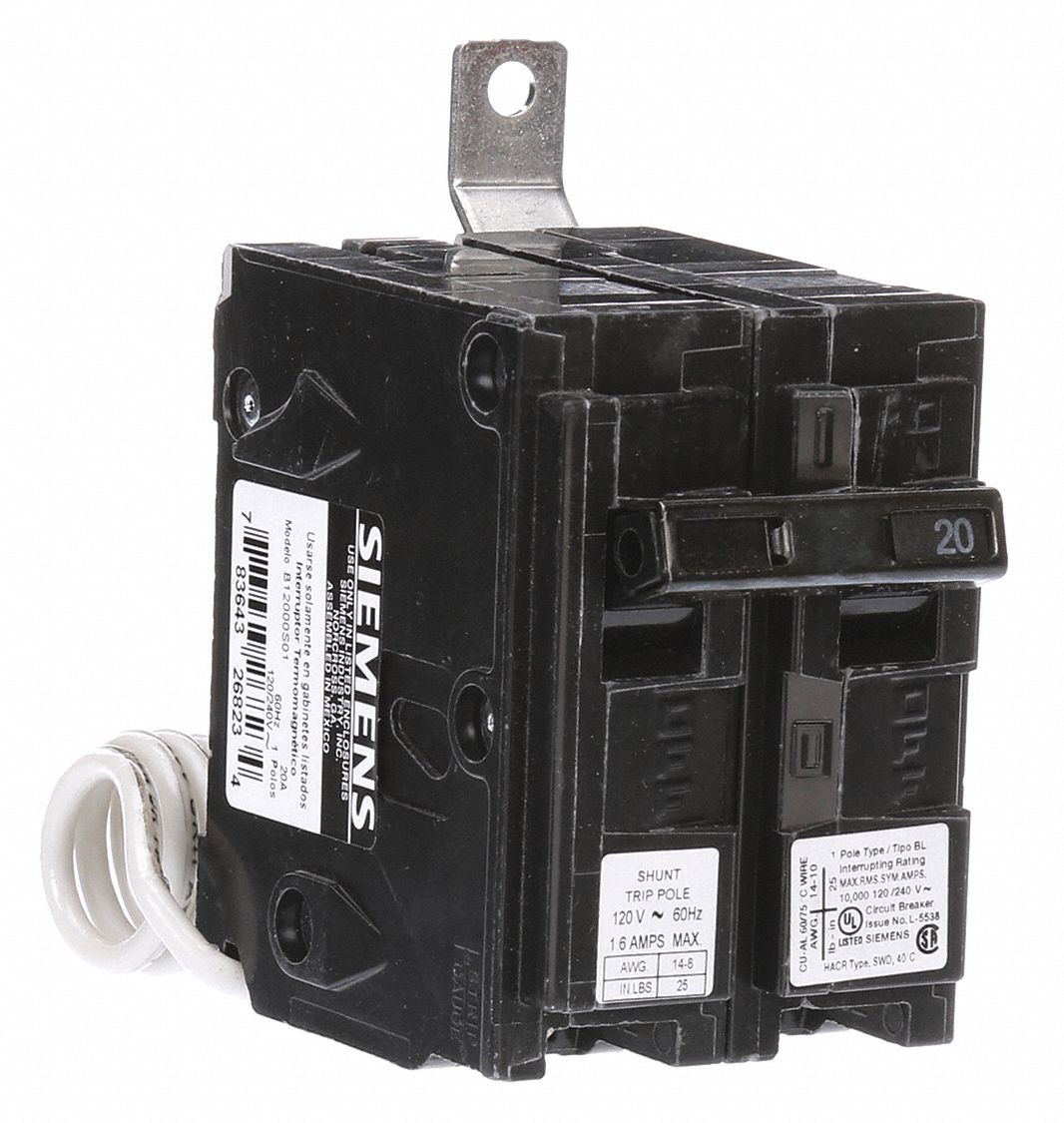
Siemens Miniature Circuit Breaker Amps 20 A Circuit Breaker Type Shunt Trip Number Of Poles 1 6euz2 B12000s01 Grainger

Wiring A Shunt Trip On Qo Circuit Breakers Schneider Electric Support Youtube
Shunt Trip Wiring Youtube
Shunt Trip Breaker Wiring Diagram Control Of Mccb Breaker Youtube
Earth Leakage Circuit Breaker Wiring Diagram Relay Fault Png Clipart Angle Area Black And White Brand

Abb S5n Breaker Wiring Second Life Storage Solar

Elevator Shunt Trip Requirements And Codes Fire Alarms Online

What Is The Cheapest Way To Shunt Trip Two 120v Circuits Under A Hood

Snt1lp03k Cutler Hammer Div Of Eaton Corp Shunt Trip Mechanism Galco Industrial Electronics

House Wiring Diagram Wire Shunt Trip Breaker Diagramwire Shunt Trip Breaker Diagram

Square D Qou2601042 Province Electric Supply
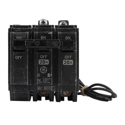
Ge Industrial Thqb2120st1 Bolt On Mount Type Thqb Miniature Circuit Breaker With Shunt Trip 2 Pole 20 Amp 120 Volt Ac

Elevator Shunt Trip Requirements And Codes Fire Alarms Online
2
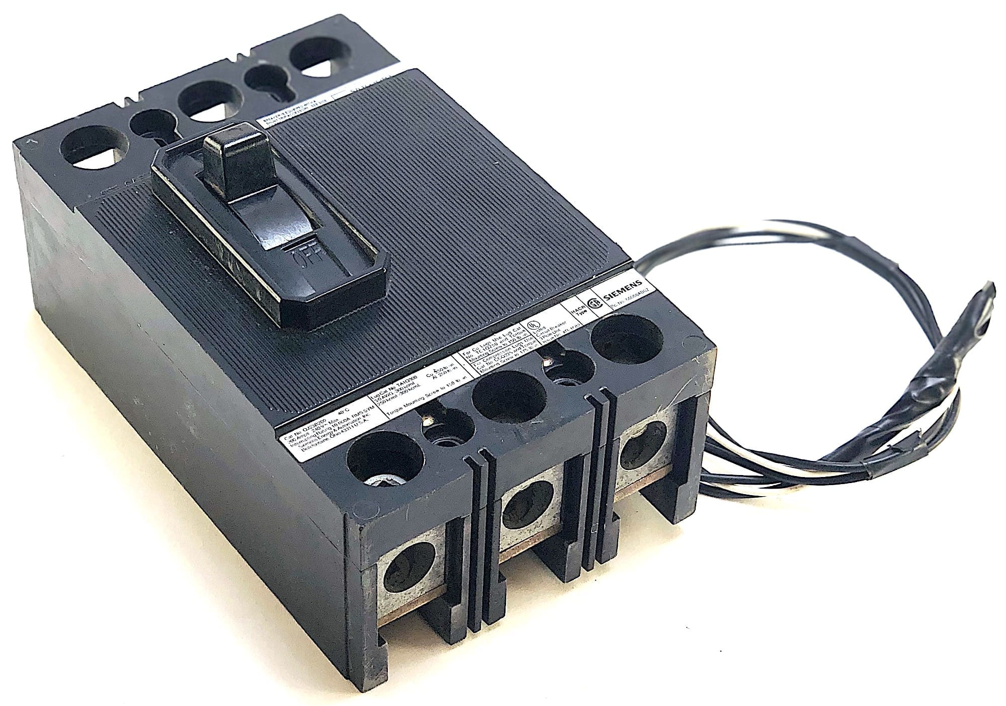
Siemens 3 Pole 200 Amp 240 Vac Circuit Breaker W Shunt Trip W2 Electrical Power And Control Consultants


Comments
Post a Comment